Upright for a shading system, removable flange of the upright and corresponding coupling means

a shading system and upright technology, applied in the direction of door/window protective devices, building components, constructions, etc., can solve the problems of increasing production costs, complicated assembly, and slow assembly speed, and is not practical nor easy to screw screws inside the threaded holes

Active Publication Date: 2021-02-16
PLASTEX
View PDF15 Cites 1 Cited by
  • Summary
  • Abstract
  • Description
  • Claims
  • Application Information

AI Technical Summary

Benefits of technology

[0018]The elastic means include a damping device comprising a channel, with a substantially C-shaped cross-section, which is mounted on an edge of the removable flange, and a flexible plastic tongue having one end on the channel and an opposite end at a distance therefrom and making contact with the base of the upright. Advantageously several damping devices may be easily and quickly mounted on the edge of the channel, with a predefined or variable spacing from each other, so as to exert a pressure along the entire flange, improving fixing inside the upright.
[0020]The removable flange comprises an end face which defines a front profile of the upright and a side wall which is perpendicular to the end face and comprises the edge on which the elastic means (damping device) are mounted. The lateral part of the flange has substantially the same length as the end face, but advantageously may be narrower than the end face, owing to the presence of the elastic means between base and flange. Also owing to its smaller width, such a flange may be more easily mounted compared to the removable flanges of the prior art.
[0025]The upright claimed in the present invention may comprise also the profiled element of the shading system and a plurality of clips 10 provided with a channel having a substantially C-shaped cross-section mounted on an edge of the profiled element, and a flexible plastic tongue 20 having one end on the channel of the clip 10 and an opposite end at a distance therefrom so as to make contact with the upright, along the inner surface of its end faces, said tongue 20 of the clip 10 acting as a spring between the profiled element and the upright, allowing the profiled element to move towards the end faces of the upright during compression or be arranged at a predefined distance when there is no compression.

Problems solved by technology

Even though widely used, the known upright has a number of drawbacks which complicate and slow down assembly and increase its production costs.
Moreover, during assembly, it is not practical nor easy to screw the screws inside the threaded holes 93, especially in view of the limited amount of space available for manoeuvre between the side walls 80, 70 and the difficulty of locating the holes 93 along the framework, once the side wall 80 has been fitted.
Often these difficulties result in incorrect assembly or damage to the end face (front portions 72, 82) of the upright.
Even following correct assembly, the aesthetic effect is not particularly satisfactory, because the front portion 92 of the removable side wall 80 in any case has holes, with the screws visible.
The application of stucco or resin in order to seal the holes is never a particularly elegant solution for the end face of the upright.

Method used


Image

  • Upright for a shading system, removable flange of the upright and corresponding coupling means
  • Upright for a shading system, removable flange of the upright and corresponding coupling means
  • Upright for a shading system, removable flange of the upright and corresponding coupling means

Examples


Embodiment Construction

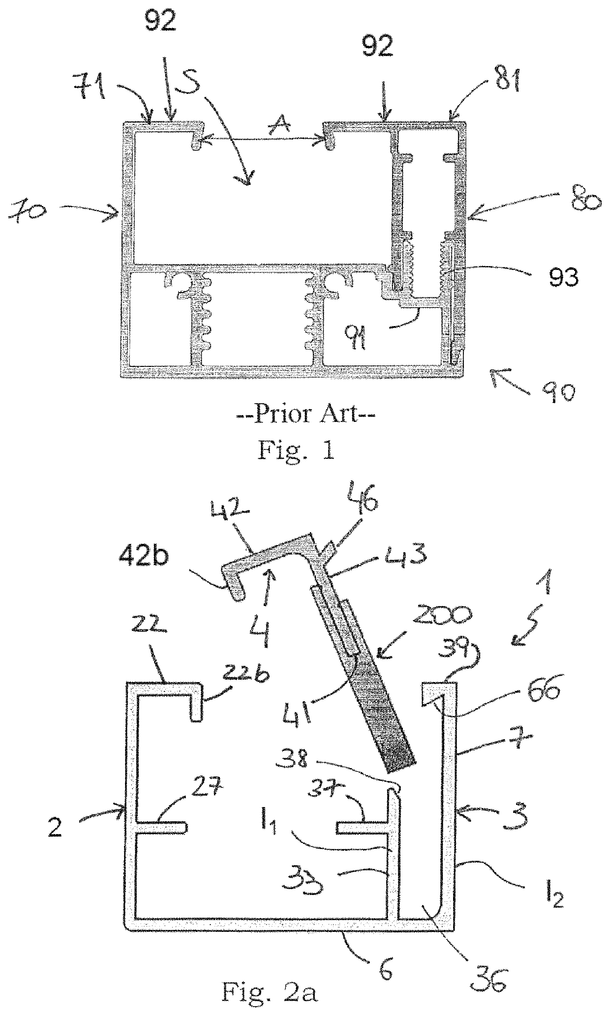
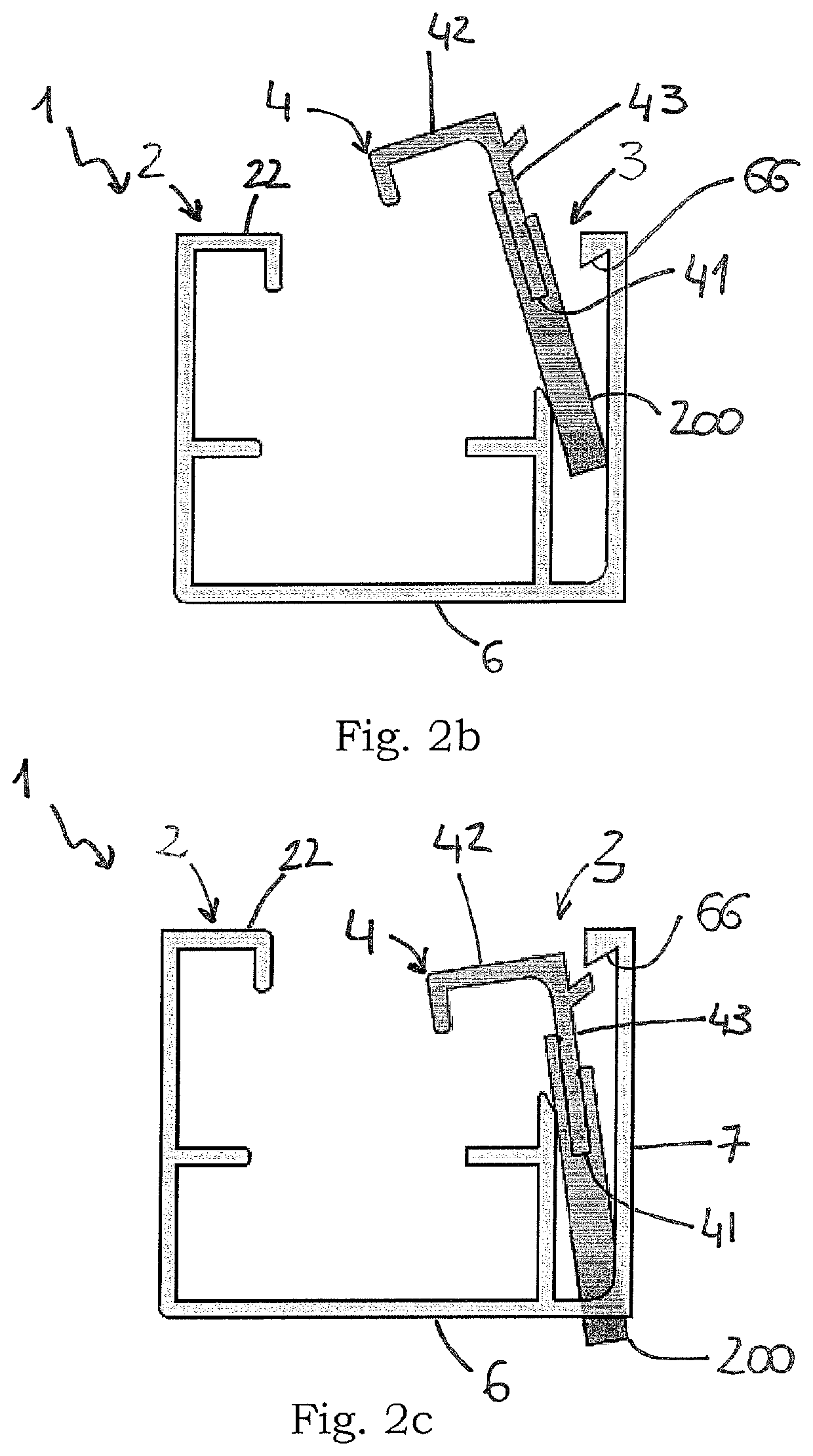
[0048]With reference to FIGS. 2a-4, these show in schematic form an upright according to the present invention and in particular an upright 1 intended to receive between its flanks 2, 3 a profiled element 100 for a shading system (FIG. 3). The profiled element 100 is associated with a screen or shading means (not shown) which extend as far as the profiled element of an oppositely arranged upright.

[0049]The upright 2a has a substantially C-shaped structure comprising a base 6 and two flanks 2, 3, preferably made as one piece. A support wall 33, parallel to one of the side faces 3, forms together with the base 6 a seat or channel 36 which runs longitudinally along all or part of the upright 1 and is designed to receive a removable flange 4 of the upright.

[0050]The flanks 2, 3 are also provided with a support surface 27, 37 for the profiled element 100 (FIG. 3), preferably made as one piece. In particular, the support surface of the flank 3 associated with the seat 36 is formed on the ...


PUM


Abstract

An upright including two flanks between which a profiled element for a shading system can be inserted is described. At least one of the flanks is associated with a removable flange, and a damping device is arranged between the removable flange and a base of the upright so as to retain the flange between the base and the flank. Furthermore, the removable flange of the upright and the damping device for fixing the flange to the upright are described. The damping device includes a channel with a substantially C-shaped cross-section which is mounted on an edge of the removable flange, and a flexible plastic tongue having one end on the channel and an opposite end at a distance therefrom and making contact with the base of the upright.

Description

FIELD OF APPLICATION[0001]The present invention relates to an upright comprising two flanks between which a profiled element for a shading system can be inserted, said profiled element being intended to receive the edge of a shading screen which extends as far as the profiled element of an oppositely arranged upright.[0002]The present invention also relates to a removable flange of the aforementioned upright, designed to allow mounting or removal of the profiled element through a front opening of the upright.[0003]The present invention also relates to means for coupling together the upright and the removable flange mentioned above.[0004]Finally, the invention relates to a simplified method for mounting a removable flange in an upright of a shading system.PRIOR ART[0005]As is known, an upright for a shading system is formed by a base and by two side walls.[0006]For example, with reference to FIG. 1, a side wall 70 is integrated in the upright 90 and the other lateral part 80 is remov...

Claims


Application Information

Patent Timeline
Patent Type & Authority Patents(United States)
IPC IPC(8): E06B9/58
CPCE06B9/58E06B2009/587
Inventor LOMBARDINI, MARCO
Owner PLASTEX
Why Eureka
Try Eureka