
Adjustable dispenser for protective adhesive film

a dispenser and adhesive film technology, applied in the direction of paper hanging, transportation and packaging, packaging, etc., can solve the problems of difficult control of the unit, inability to double the width of the dispenser, and inability to fit all the most common film roll widths, etc., and achieve the effect of easy cutting the film roll

Inactive Publication Date: 2010-12-07
EZ WALL LLC
View PDF7 Cites 2 Cited by
  • Summary
  • Abstract
  • Description
  • Claims
  • Application Information

AI Technical Summary

Benefits of technology

"The present invention is a device for dispensing rolls of protective adhesive film having different widths. The device comprises a central support assembly and a right and left support assembly each with a film mounting roller for supporting the ends of the film roll. The device also includes a handle. The technical effects of the invention include accommodating rolls of film having widths of 24 inches, -30 inches, -36 inches, and -48 inches while keeping the handle in the center of the dispenser, allowing for easy and quick mounting or changing of the film pressing tube and film roll, and allowing a user to easily cut the roll of film with the handle resting on the ground and moveable to keep the film taught during cutting."

Problems solved by technology

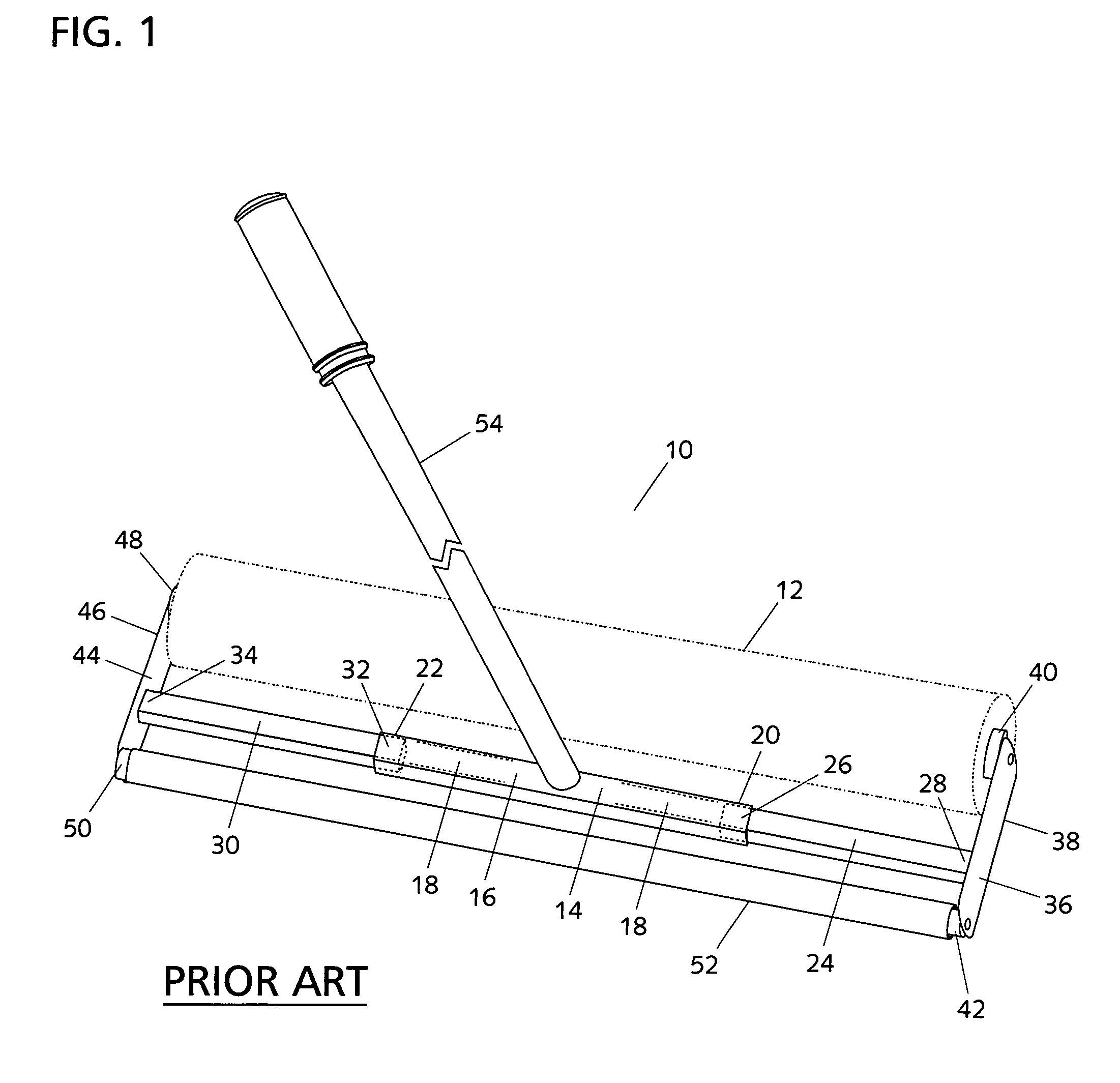
One significant problem with device 10 is that it cannot double its width and cannot fit all of the most common film roll widths, namely, 24 inches, 30 inches, 36 inches, and 48 inches.
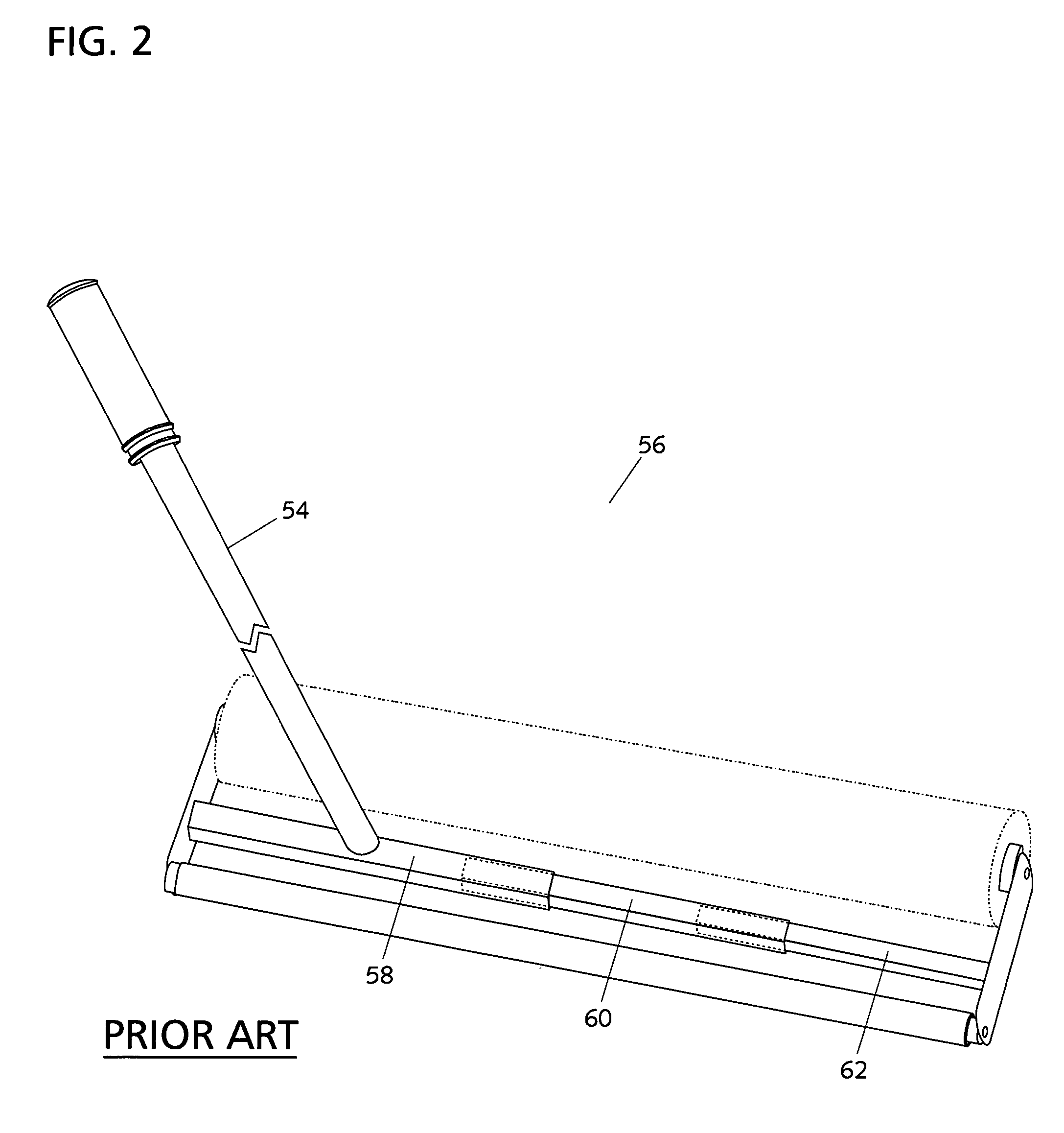
One significant problem with device 56 is that handle 54 is not always centered on the dispenser at widths greater than 24 inches thereby making it difficult to control the unit.
This creates a clumsy operation for a person working alone, especially with large heavy rolls of film.

Method used


Image

  • Adjustable dispenser for protective adhesive film
  • Adjustable dispenser for protective adhesive film
  • Adjustable dispenser for protective adhesive film

Examples


Embodiment Construction

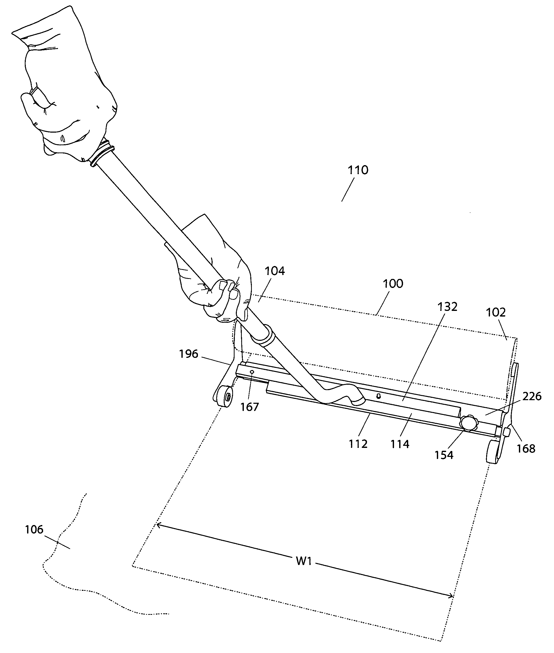
[0026]Referring to FIGS. 5-7, the present invention is a device 110 for dispensing rolls of protective adhesive film 100 having different widths upon a floor surface 106. Film roll 100 has first and second end portions 102 and 104, and a width W1. As commonly used in the industry, width W1 of film roll 100 is 24 inches, 30 inches, 36 inches or 48 inches.

[0027]Device 110 generally comprises a central support assembly 112, a right support assembly 168, a left support assembly 196, a pressing tube kit 224 (FIG. 11), and a handle 258. FIGS. 5 and 6 show the device 110 fully retracted for dispensing a roll of film 100 having a width of 24 inches using a first pressing tube 226 (to be described) of pressing tube kit 224. FIG. 7 shows the device 110 fully extended for dispensing a roll of film 100 having a width of 48 inches using second and third pressing tubes 240 (to be described) of pressing tube kit 224.

[0028]Referring to FIGS. 7 and 12, central support assembly 112 generally comprise...


PUM

PropertyMeasurementUnit
widthsaaaaaaaaaa
widthsaaaaaaaaaa
widthsaaaaaaaaaa

Abstract

The present invention is a device for dispensing rolls of protective adhesive film having different widths. In one embodiment, the device comprises a central support assembly comprising first and second elongated members having a first longitudinal axis and a second longitudinal axis, respectively. The first longitudinal axis of the first elongated member is off-set from the second longitudinal axis of the second elongated member. The central support assembly further comprises first and second extension members each having a first portion telescopically engaged with the first and second elongated members, respectively, and a second portion. The device further comprises a right support assembly engaged with the second portion of the first extension member and comprising a film mounting roller adapted to support the first end portion of the roll of film. The device further comprises a left support assembly engaged with the second portion of the second extension member and comprising a film mounting roller adapted to support the second end portion of the roll of film. The device further comprises a handle engaged with the central support assembly. In use, the first and second extension members may be extended or retracted from the first and second elongated members, respectively, to accommodate film roll widths of 24 inches, 30 inches, 36 inches, or 48 inches. At any film width, the handle is centered between the right and left support assembly.

Description

CROSS-REFERENCE TO RELATED APPLICATIONS[0001]This applications claims priority to U.S. Provisional Application No. 60 / 869,956 filed on Dec. 14, 2006, now pending, which is hereby incorporated into this specification by reference in its entirety.BACKGROUND OF THE INVENTION[0002]Adhesive films are often used to protect carpeting and other floor finishes. There is a continuing need for a dispenser to make application of the film faster and easier. The most common roll widths are 24 inches, 30 inches, 36 inches, and 48 inches. Some manufacturers offer a dispenser that accommodates each roll width and others offer a dispenser that accommodates several different widths.[0003]FIG. 1 shows a prior art device 10 that can accommodate several widths of film roll 12. Device 10 has a central support assembly 14, a right support assembly 36, a left support assembly 44, a film pressing tube 52, and a handle 54. Right support assembly 36 has a bracket 38, a film mounting roller 40 adapted to receiv...

Claims


Application Information

Patent Timeline
Patent Type & Authority Patents(United States)
IPC IPC(8): B65B41/16
CPCB65H35/0006E04G21/30B65H2701/1752Y10T156/1795Y10T156/18Y10T156/1788
Inventor MELINO, SR., CHARLES E.MELINO, JR., CHARLES
Owner EZ WALL LLC
Learn More