Hose element

a technology of hose elements and claws, which is applied in the direction of mechanical equipment, milking devices, catheters, etc., can solve the problems of difficult to mount separate tools, complicated and time-consuming manual work to be performed by dairy farmers, and difficulty in achieving the effect of easy and quick mounting

Inactive Publication Date: 2010-07-01
DELAVAL HLDG AB
View PDF0 Cites 1 Cited by
  • Summary
  • Abstract
  • Description
  • Claims
  • Application Information

AI Technical Summary

Benefits of technology

[0003]The object of the present invention is to remedy the disadvantages mentioned above. More specifically, the object of the present invention is to provide a hose element which can be easily and quickly mounted to another element, especially in an aperture of a claw of a milking member.
[0011]According to a further embodiment of the invention, also the mounting member comprises a primary engagement part extending axially from the primary portion. Advantageously, the primary engagement part and the secondary engagement part are disposed diametrically opposite to each other. In such a way, the user may easily grip the hose element and perform the above-mentioned compressing operation by pressing the two engagement parts towards each other. Furthermore, the primary engagement part and the secondary engagement part may be connected to a common connection part extending around the hose portion in a peripheral direction. Advantageously, the connection part may be an integrated part of the mounting member and made in the second material. Also the primary engagement part may have an elongated shape.

Problems solved by technology

The hose element is elastic but still rather stiff, which means that the pressure to be applied to the first end portion is significant.
Consequently, the mounting of the hose element in the aperture of the claw is a complicated and time-consuming manual work to be performed by the dairy farmer.
However, such a loose tool has to be carried around by the farmer in order to be at hand when needed.
Furthermore, such a separate tool can easily disappear.

Method used


Image

  • Hose element
  • Hose element
  • Hose element

Examples


Embodiment Construction

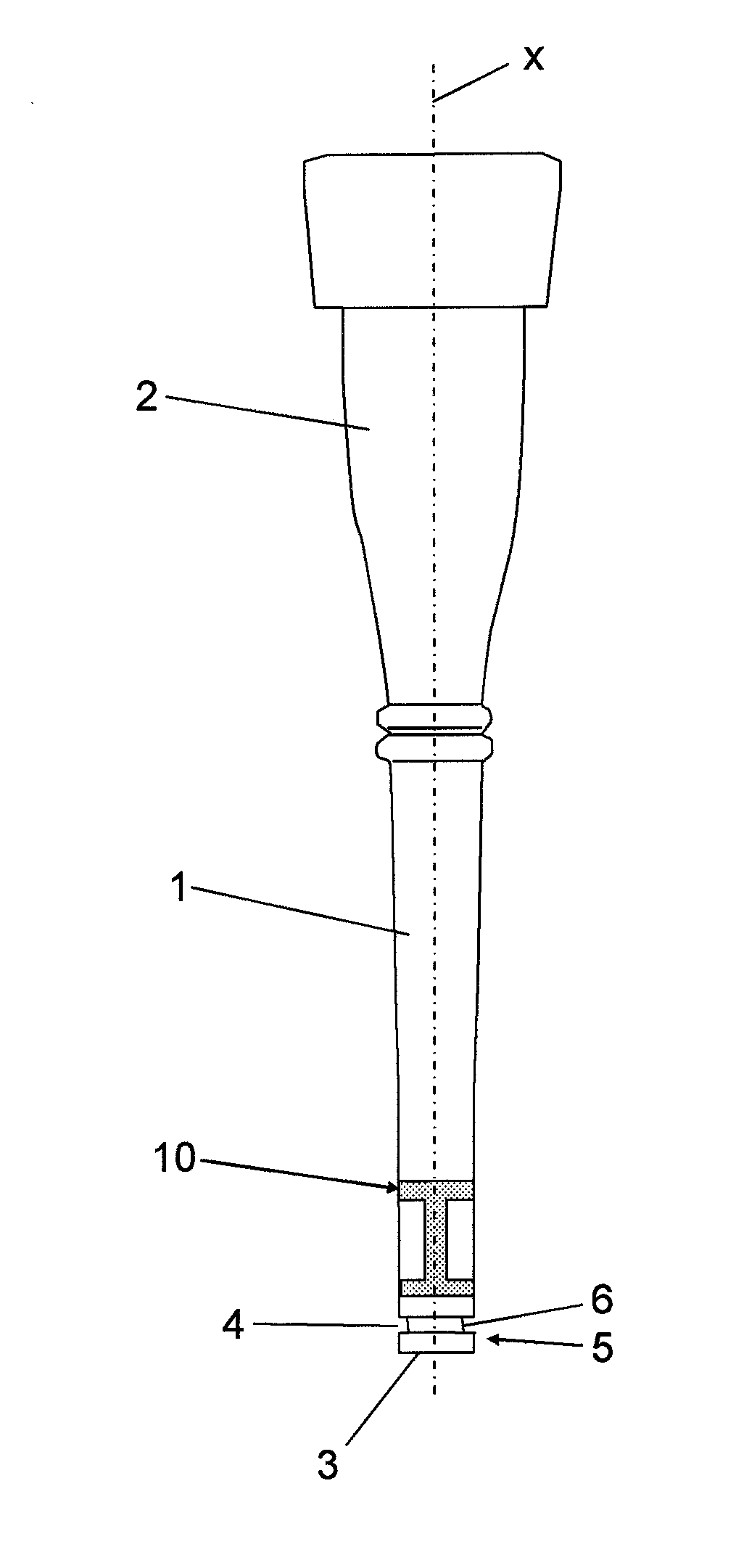
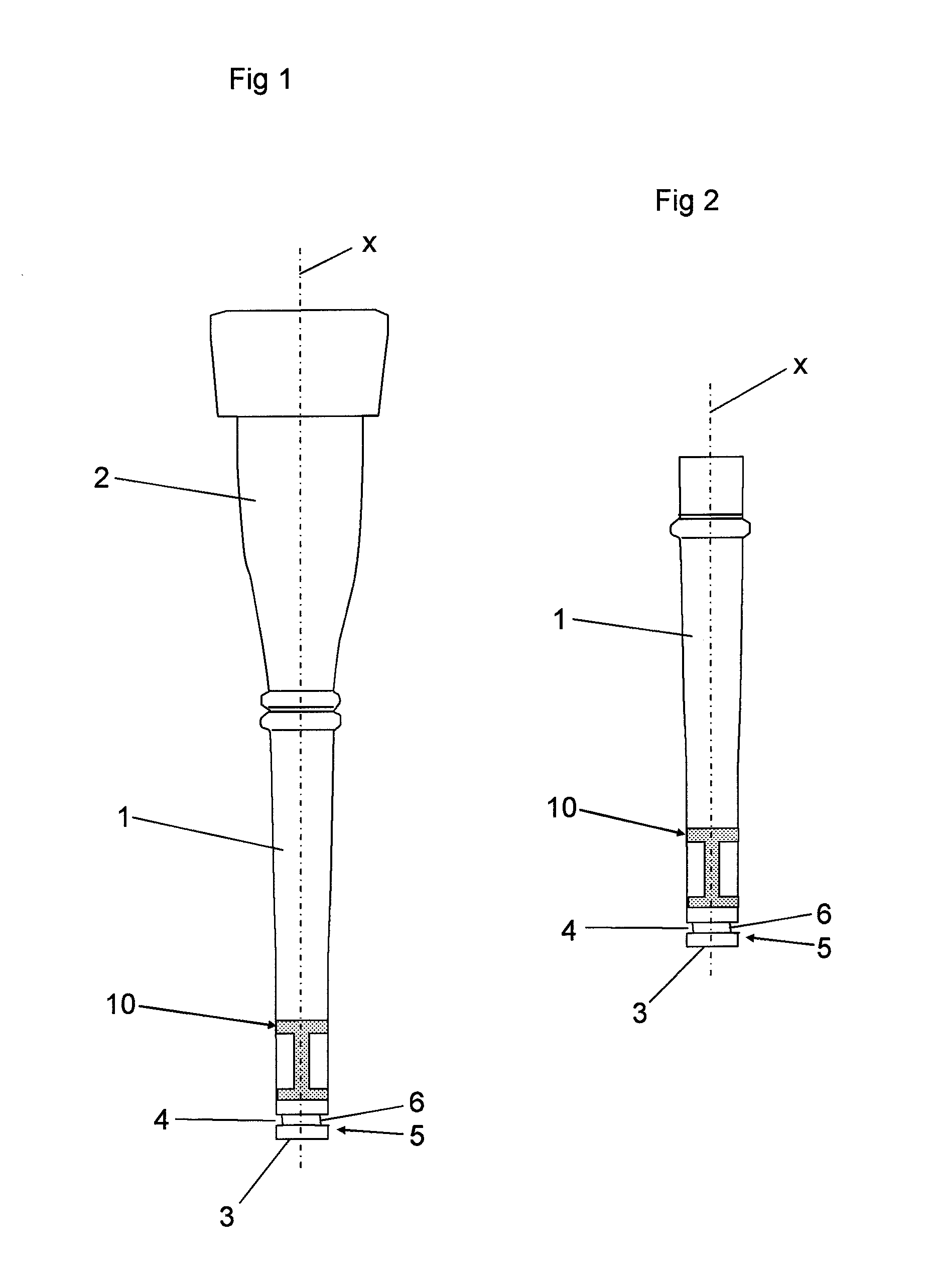
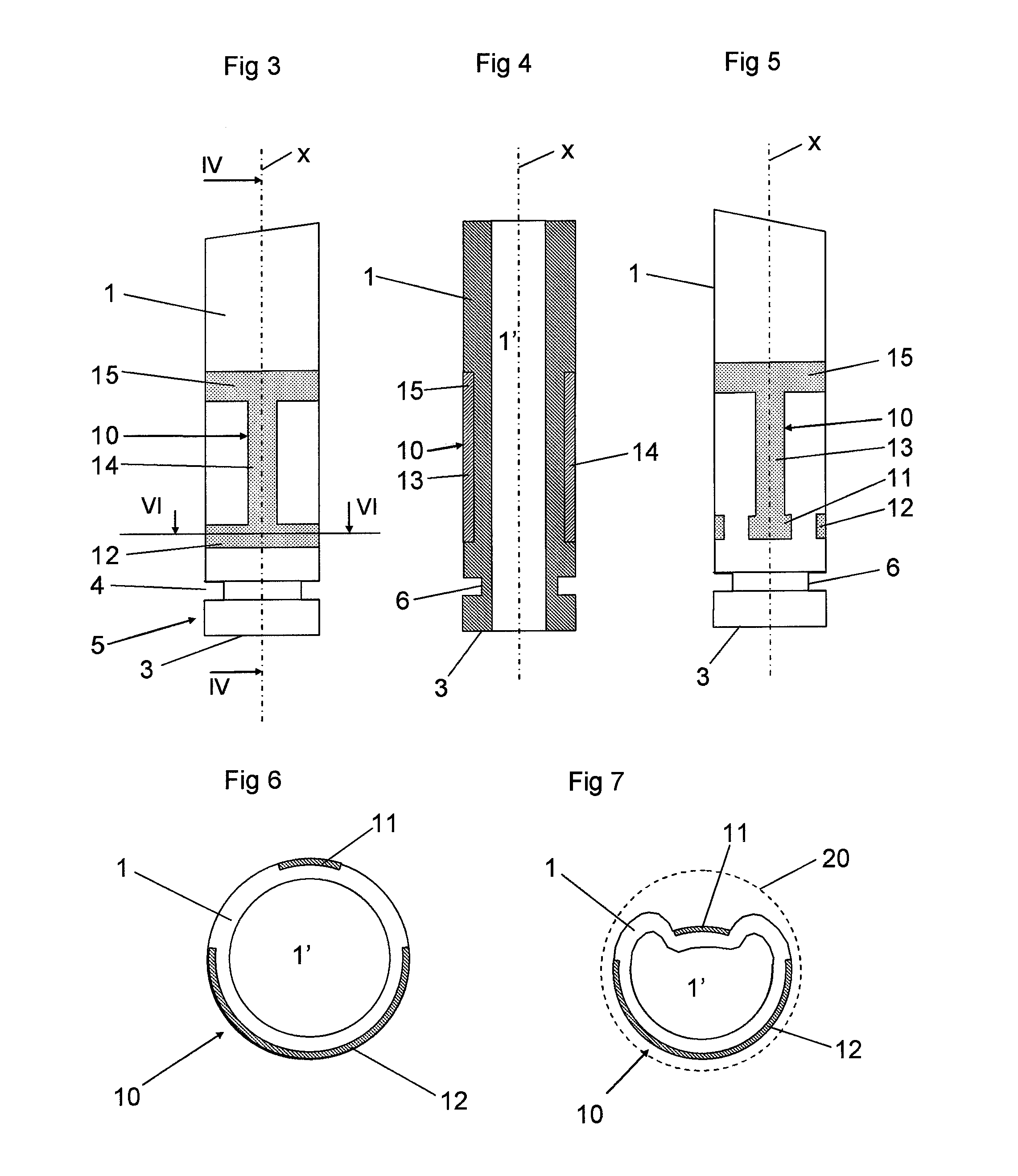
[0028]FIG. 1 discloses a hose element, which is configured for transporting milk and comprises a hose portion 1 and a teat cup liner portion 2 adapted to be mounted in a teat cup shell (not disclosed) to form a teat cup. The hose element is tubular and defines an inner channel 1′, see FIG. 4. The hose element has a first end 3. The hose portion 1 extends from the first end 3 along a longitudinal centre axis x of the hose element and the teat cup liner. In the embodiments disclosed, the hose portion 1 has, in a rest state, a circular, or substantially circular, cross-section. The hose portion may also have another cross-sectional shape, for instance an oval shape. The hose portion 1 is manufactured in a first material. The teat cup liner portion 2 may also be manufactured in the first material. The first material could be any suitable material normally used for teat cup liners, for instance natural or synthetic rubber, TPE, Thermal Plastic Elastomer, silicone elastomer or any other s...


PUM

PropertyMeasurementUnit
sizeaaaaaaaaaa
elasticaaaaaaaaaa
elongated shapeaaaaaaaaaa

Abstract

A hose element is configured for a milking device. The hose element includes a first end (3) and a hose portion (1) of a first material. The hose portion extends from the first end along a longitudinal centre axis (x) and has an outer size in a radial plane with respect to the longitudinal centre axis. An attachment section (4) extends around the hose portion in a peripheral direction in the proximity of the first end. The hose element includes a mounting member (10) of a second material which is joined to the hose portion (1). The mounting member includes a primary portion (11), which is joined to the hose portion (1) in the proximity of the attachment section and configured to permit, when being pressed inwardly towards the longitudinal centre axis, a reduction of the outer size of the hose portion at an end portion (5).

Description

[0001]The present invention refers to a hose element according to the preamble of claim 1.[0002]Such a hose element may be a part of a teatcup liner or a short milk conduit of a milking member. In a usual application, the first end portion of the hose element is configured to be attached to a claw of the milking member. Typically, the first end portion of the hose element is intended to be introduced into an aperture of the claw in such a way that the groove receives and engages the edge defining the aperture. The first end portion is thus compressed to permit introduction into the aperture. After releasing of the compressing pressure, the first end portion resumes its normal shape, whereby the edge is permitted to enter the groove so that the first end portion is securely mounted in the aperture of the claw. The hose element is elastic but still rather stiff, which means that the pressure to be applied to the first end portion is significant. Furthermore, the pressure is to be dist...

Claims


Application Information

Patent Timeline
Patent Type & Authority Applications(United States)
IPC IPC(8): A01J3/00A01J5/16
CPCA01J5/044F16L47/26F16L11/122A01J5/08F16L47/28
Inventor ALVEBY, NILS
Owner DELAVAL HLDG AB
Why Eureka
Try Eureka