
Pseudo-satellite transmitter and method of transmitting GPS signals using pseudo-satellite transmitter

a pseudo-satellite transmitter and gps technology, applied in satellite radio beaconing, measurement devices, instruments, etc., can solve the problems of interference between a signal with a weak power level and a signal with a strong power level, poor quality of the received signal,

Inactive Publication Date: 2010-07-15
SAMSUNG ELECTRONICS CO LTD
View PDF0 Cites 8 Cited by
  • Summary
  • Abstract
  • Description
  • Claims
  • Application Information

AI Technical Summary

Benefits of technology

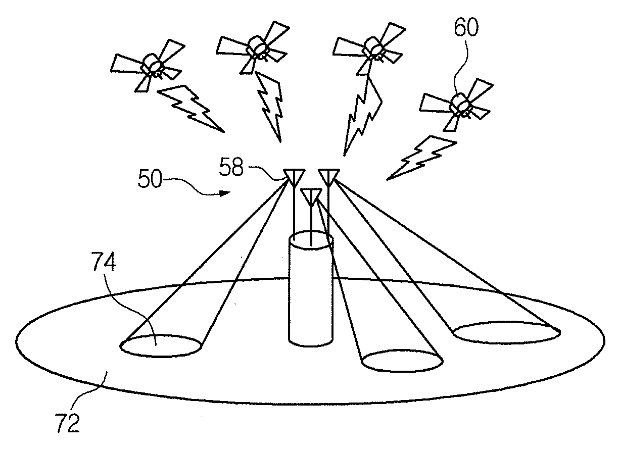
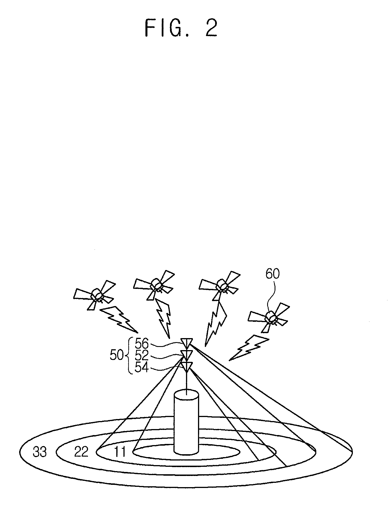
The patent describes a method of transmitting GPS signals from a pseudo-satellite. The method involves generating multiple GPS signals with different power levels based on the GPS signal and power determination values of multiple reception areas. These signals are then transmitted through different antennas to the reception areas. The technical effect of this method is to improve the accuracy and reliability of GPS navigation in areas where GPS signals may be weaker or absent.

Problems solved by technology

The technical problem addressed in this patent is the need for a GPS system that can improve GPS calculations by interfacing with a pseudo-satellite that can provide additional GPS signals in environments where GPS signals may be limited or interfered with.

Method used


Image

  • Pseudo-satellite transmitter and method of transmitting GPS signals using pseudo-satellite transmitter
  • Pseudo-satellite transmitter and method of transmitting GPS signals using pseudo-satellite transmitter
  • Pseudo-satellite transmitter and method of transmitting GPS signals using pseudo-satellite transmitter

Examples


Embodiment Construction

[0023]Exemplary embodiments of the inventive concept will now be described more fully with reference to the accompanying drawings. Inventions based on the inventive concept may, however, be embodied in many different forms and should not be construed as limited to the exemplary embodiments set forth herein. Like numbers refer to like elements throughout the description of the figures.

[0024]It will be understood that when an element is referred to as being “connected” or “coupled” to another element, it can be directly connected or coupled to the other element or intervening elements may be present. Hereinafter, a pseudo-satellite transmitter and a method of transmitting GPS signals using a pseudo-satellite transmitter according to exemplary embodiments of the inventive concept will be described in detail with reference to the accompanying drawings.

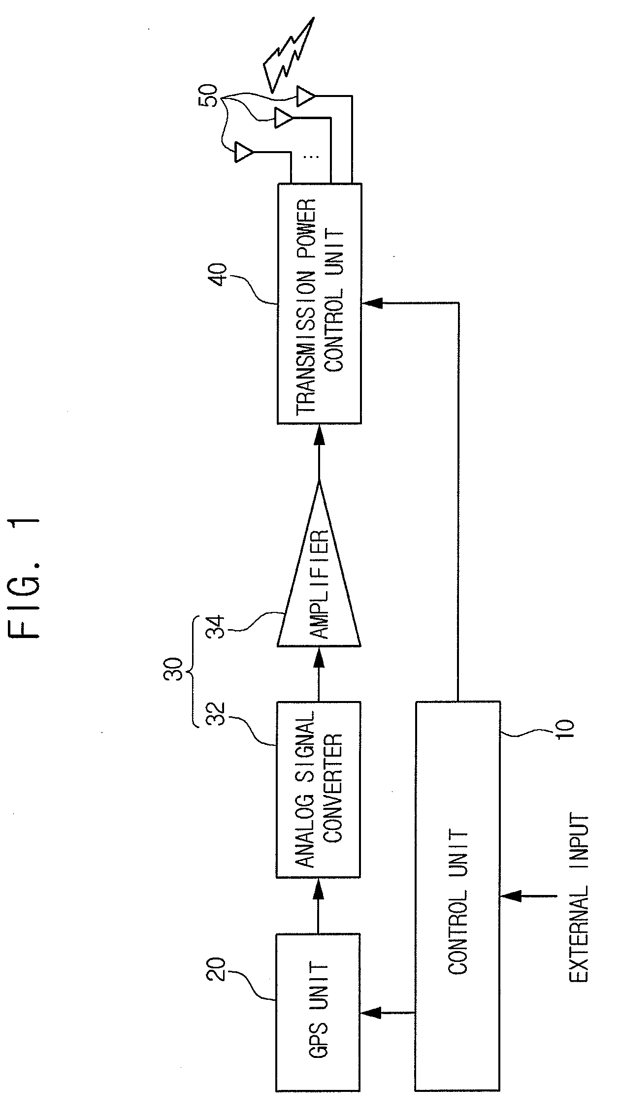
[0025]FIG. 1 is a block diagram schematically illustrating a pseudo-satellite transmitter according to an exemplary embodiment of the inv...


PUM


Abstract

A pseudo-satellite transmitter includes a GPS unit, a transmission power control unit, and a plurality of antennas. The GPS unit generates a GPS signal of a pseudo-satellite. The transmission power control unit generates a plurality of GPS signals having different power levels based on the GPS signal generated by the GPS unit and a distance from a shadow area to the pseudo-satellite transmitter. Each antenna is configured to wirelessly transmit the GPS signals with different power levels output from the transmission power control unit to a corresponding one of a plurality of shadow areas according to the distance from the shadow area to the corresponding antenna.

Description


Claims


Application Information

Patent Timeline
Owner SAMSUNG ELECTRONICS CO LTD
Learn More