Satellite transmitter system

a satellite transmitter and transmitter module technology, applied in the direction of electrical apparatus construction details, sustainable buildings, high-level techniques, etc., can solve the problems of increasing power requirements for uplink data signal transmission, heavy and cumbersome carrying and setting up, and conventional transmitter modules

Active Publication Date: 2017-10-24
MISSION MICROWAVE TECH INC
View PDF18 Cites 4 Cited by
  • Summary
  • Abstract
  • Description
  • Claims
  • Application Information

AI Technical Summary

Benefits of technology

[0008]A satellite uplink transmitter module for transmitting signals for uplink signal transmission in a satellite communication system includes a transmitter unit that includes i) transmitter circuitry, ii) an input signal port, iii) and a transmit output signal port, the transmitter circuitry generating heat. The transmitter circuitry may contain frequency conversion circuitry to convert from a typically lower-frequency modem signal to a typically higher-frequency radio frequency (RF) satellite uplink signal. The transmitter circuitry may also contain amplification circuitry to increase the typically lower-power input signal to a higher-power output signal suitable for communication with a distant satellite. The satellite uplink transmitter module also includes at least one heat sink coupled to the transmitter unit, the at least one heat sink including a plurality of heat sink fins, wherein at least two of the plurality of heat sink fins are of different heights and an air fan capable of generating air flow parallel with the heat sink fins. The satellite uplink transmitter module includes an outer enclosure that i) encloses the transmitter unit and the plurality of heat sink fins and ii) is impermeable to the air flow generated by the air fan, the outer enclosure including an enclosure cross section shape that is substantially similar to a heat sink cross section shape that is defined by the height of each of the plurality of the heat sink fins.

Problems solved by technology

As a result, conventional transmitter modules include a rectangular (or square) cross sectioned form factor and are extremely heavy and cumbersome to carry and to set up, especially for use out in the field.
However, in order to achieve these higher uplink data rates, the power requirements for uplink data signal transmission increases, together with the heat produced by the transmitter circuitry (e.g., a microwave power amplifier) are considerable.
As these power levels increase, the conventional transmitter block upconverter modules with rectangular or square cross sections continue to grow, resulting in very large and heavy units that are inefficient at properly dissipating heat from the transmitter circuitry.
The importance of reducing the satellite transmitter's size and weight cannot be overstated for these portable applications.
These heat sink fins of equal height utilized within a conventional transmitter block dissipate heat extremely inefficiently with regard to their size and weight, because the heat sink fins located at the areas of greatest heat levels generated by the transmitter circuitry are of the same height as the heat sink fins located at the lowest heat levels.
These underutilized heat sink fins furthest from the areas of greatest heat levels add unnecessary weight and size to the overall block transmitter.
This extra weight and size of these underutilized heat sink fins leads to higher material costs to build a conventional block transmitter and detracts from the portability of the unit.
Furthermore, because most air fans include rotating fan blades that form a circular cross section, managing the air flow within a rectangular cross section of a transmitter coupled with a circular cross sectioned air fan or fans is difficult and more costly.
For example, using a circular fan that includes circular vanes and fan blades that form a circular cross section coupled with a rectangular-cross-section transmitter may lead to air flow distribution issues, air pressure differential issues, etc.
A similar issue occurs when using a row of several circular fans; a pressure-equalizing plenum is needed to ensure proper airflow across the heat sinking fins.
However, utilizing one or more plenum, again, adds weight and volume to the transmitter unit.

Method used


Image

  • Satellite transmitter system
  • Satellite transmitter system
  • Satellite transmitter system

Examples


Embodiment Construction

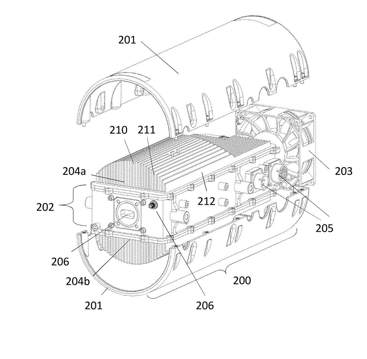
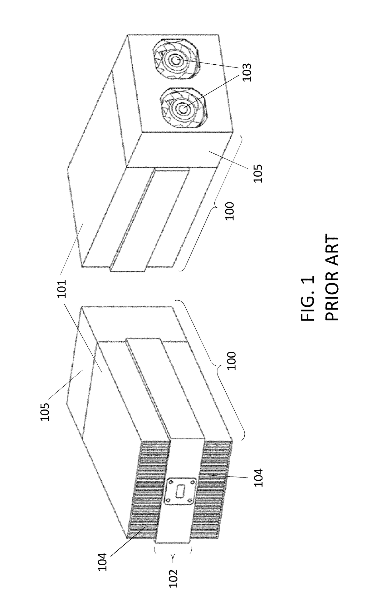
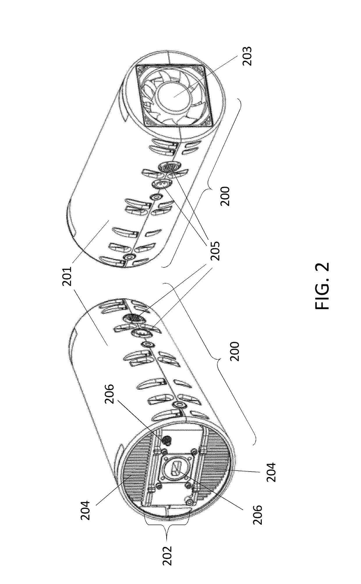
[0022]Generally speaking, a satellite transmitter system includes a transmitter module that, via its rounded form factor, more efficiently dissipates high levels of heat that is generated while converting and amplifying lower frequency and lower power data signals into higher frequency and higher power satellite transmission signals (i.e., “upconverting” and “amplifying”). For example, the uplink transmitter module may be coupled with a rounded cross sectioned fan that allows for more even and optimized airflow distribution (i.e., better heat dissipation) within the rounded form factor of the transmitter module. Moreover, the transmitter module may include one or more heat sinks coupled to a transmitter unit that processes frequency conversions and amplifications, generating the high levels of heat. Importantly, each heat sink may include a plurality of heat sink fins, and depending on the heat level generated at particular location of the transmitter unit, a differently sized heat ...


PUM


Abstract

A satellite transmitter module for accepting input signals and emitting output signals for uplink transmission. The module includes a transmitter unit that includes i) transmitter circuitry, ii) at least one input port, iii) and at least one output port. At least one heat sink coupled to the transmitter unit includes a plurality of heat sink fins, wherein at least two of the plurality of heat sink fins are of different heights. A fan is capable of generating air flow parallel with the plurality of heat sink fins. The module further includes an outer enclosure that i) encloses the transmitter unit and the plurality of heat sink fins and ii) is impermeable to the air flow generated by the fan. The outer enclosure includes an enclosure cross section shape that is substantially similar to the at least one heat sink cross section shape defined by the height of each of the plurality of the heat sink fins.

Description

CROSS-REFERENCE TO RELATED APPLICATION[0001]This application is the nonprovisional application of provisional application, Ser. No. 62 / 132,941, filed on Mar. 13, 2015, which is incorporated by reference in its entirety herein.FIELD OF INVENTION[0002]This disclosure generally relates to a satellite transmitter system, and more specifically, to a satellite transmitter system that includes a transmitter module capable of more efficiently dissipating heat.BACKGROUND[0003]Terrestrial satellite transmitter systems are used for uplink signal transmissions in satellite communications. Generally, a satellite transmitter system includes an upconverter module that converts lower frequency modem data signals into higher frequency signals for an uplink signal transmission to a satellite and / or a power amplifier to increase the power of these higher frequency signals to levels adequate to reach the distant satellite with sufficient strength. Moreover, these transmitters are often referred to as a...

Claims


Application Information

Patent Timeline
Patent Type & Authority Patents(United States)
IPC IPC(8): H04B1/38H04B1/04H04B7/185H04B1/036H05K7/20
CPCH04B7/18515H04B1/036H05K7/20136H04B1/04Y02B60/50H04B2001/0491H04B1/02H04B1/03Y02D30/70
Inventor AURICCHIO, JR., FRANCIS SFIELDHOUSE, DAVID
Owner MISSION MICROWAVE TECH INC
Why Eureka
Try Eureka