
Lamp structure with low temperature feature

a technology of low temperature and light source, which is applied in the direction of lighting and heating apparatus, semiconductor devices for light sources, and support devices for lighting, etc. it can solve the problems of no benefit in fact to the global warming situation, the blackout method aforesaid is not good, and the frequency of world climatic abnormalities has already soared and worsened year by year, so as to reduce the thermal energy, prolong the service life, and effectively absorb and dissipate thermal energy

Inactive Publication Date: 2009-04-23
CHANG
View PDF4 Cites 15 Cited by
  • Summary
  • Abstract
  • Description
  • Claims
  • Application Information

AI Technical Summary

Benefits of technology

"The present invention is a lamp structure with low temperature features that can effectively absorb and dissipate the thermal energy generated within it. The lamp includes an illuminating part with multiple light emitting diode (LED) chips that provide the required illuminating luminance while reducing the amount of heat generated. The heat sink is integrated with the illuminating part to conduct the thermal energy to the lamp body. A reflector is placed over the illuminating part to promote the illuminating range and angle. The frame cover is made of potassium glass with impact-resistant and refractory properties to protect the lamp. A fixing plate is placed over the outer rim of the frame cover to securely fix all the components to the lamp body. The lamp structure with low temperature features can provide both an improved illuminating effect and a reduction in heat generation, promoting environmental protection."

Problems solved by technology

As greenhouse effects due to global warming result being more obvious, the frequency of world climatic abnormality has already soared and worsened year by year.
Thus, there is no benefit in fact to the global warming situation.
But the blackout method aforesaid is not a good way because the lamps are mainly used for the illumination.
Thus, the conventional lamps, which still exists some drawbacks, at present is indeed not a good contrivance for being unable to overcome the issue on the heat source effectively.

Method used


Image

  • Lamp structure with low temperature feature
  • Lamp structure with low temperature feature
  • Lamp structure with low temperature feature

Examples


Embodiment Construction

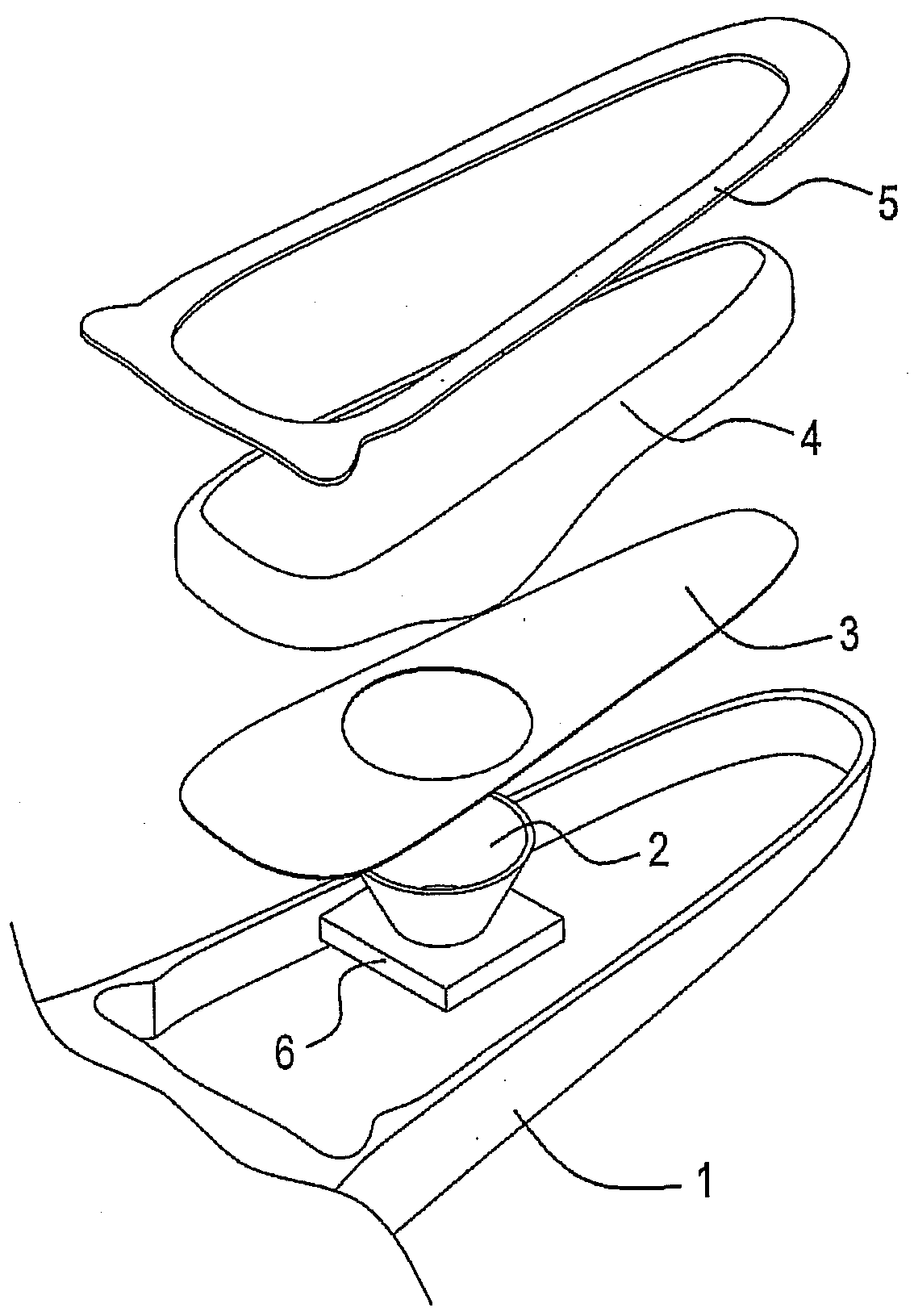
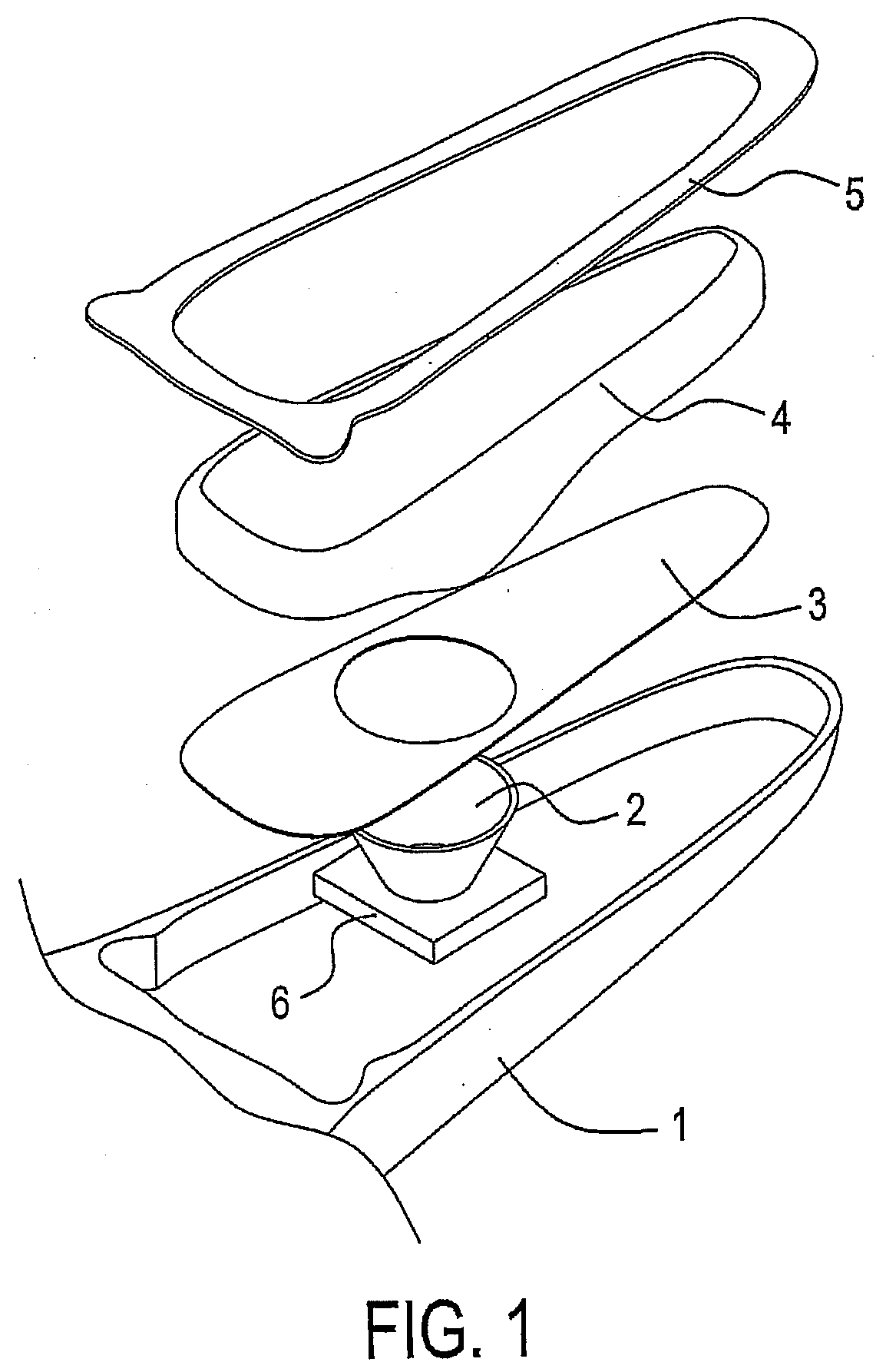
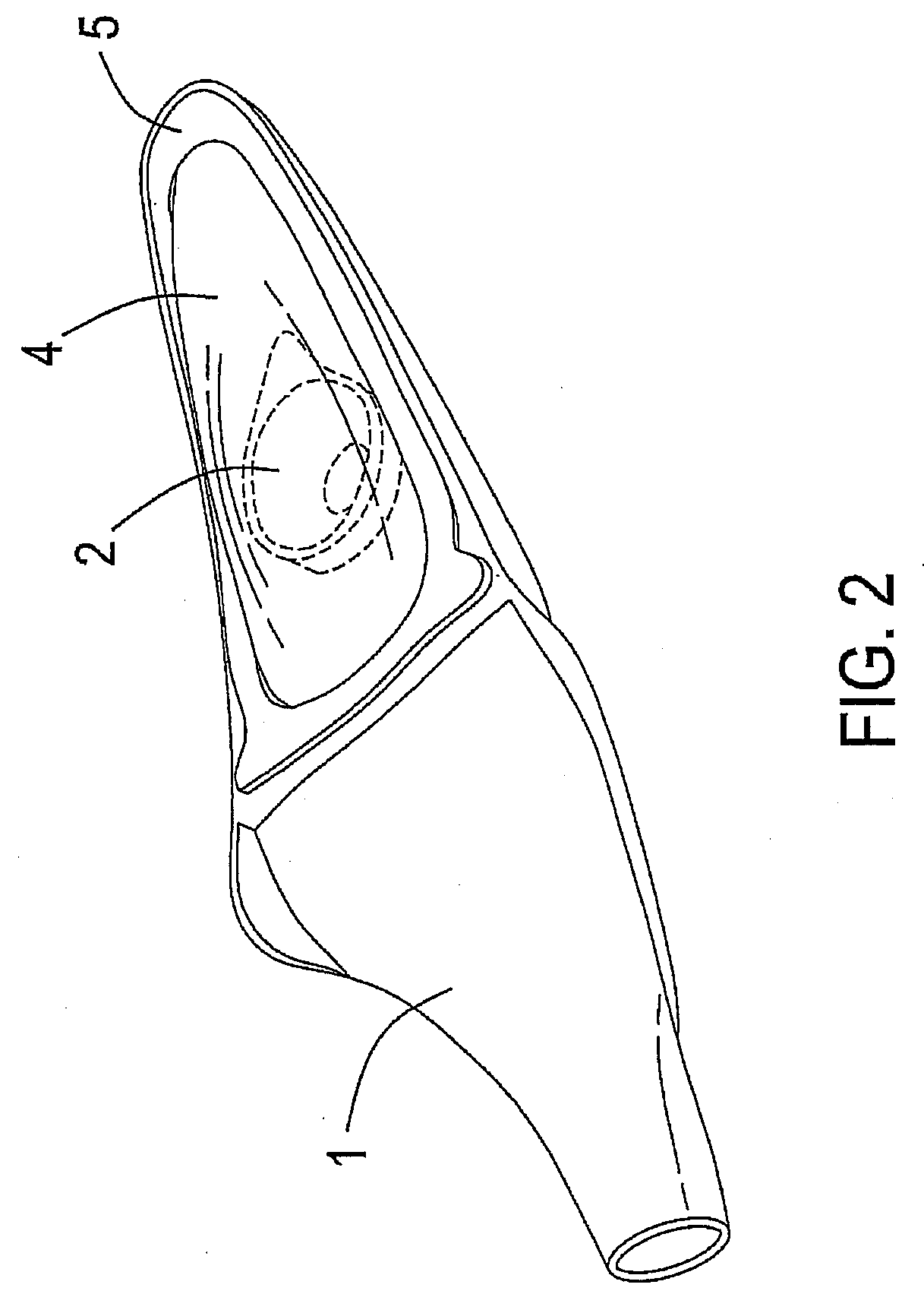
[0020]Please refer to the FIGS. 1 through 3, which are the perspective exploded and combinational views of the lamp structure with low temperature feature for the present invention. The lamp structure with low temperature feature comprises a lamp body 1, an illuminating part 2, a heat sink 6, a reflector 3, a frame cover 4 and a fixing plate 5, wherein said lamp body 1 is a founded alloy of various metals by fusing in multi-stage heating process for effectively absorbing and dissipating the thermal energy generated by the illuminating part 2 so as to effectively maintain the normal operating ambient temperature in the lamp; said illuminating part 2, which is connected to the lamp body 1, includes plural LED chips to achieve the required illuminating luminance and significantly decrease the thermal energy generated therein as well as effectively prolong the service life thereof; said heat sink 6 is firmly integrated at the base of the illuminating part 2 mutually for effectively diss...


PUM


Abstract

A fluorescent lamp holder combination device includes a main lamp holder and an auxiliary lamp holder set, which is provided with an auxiliary lamp holder. The main lamp holder is internally configured with a multifunction ballast, which is electrically connected to a conducting portion. Each of the conducting portions is electrically connected to a connecting portion of each of the auxiliary lamp holders by means of a set of conducting cables, thereby enabling parallel connection between each of the auxiliary lamp holders using the single multifunction ballast, and achieving the effectiveness to enable the single multifunction ballast to provide stable rectification and energy saving for the auxiliary lamp holders. Furthermore, a starting capacitor and current-limiting inductor can be disposed within each of the auxiliary lamp holders, thereby reducing use-cost of the set of conducting cables while facilitating maintenance of the starting capacitors and the current-limiting inductors.

Description

BACKGROUND OF THE INVENTION[0001](a) Field of the Invention[0002]The present invention relates to a lamp structure with low temperature feature, particularly for one having lamp body been founded alloy of various metals by fusing in multi-stage heating process for effectively absorbing and dissipating the thermal energy generated therein so as to effectively maintain the normal operating ambient temperature in the lamp.[0003](b) Description of the Prior Art[0004]As greenhouse effects due to global warming result being more obvious, the frequency of world climatic abnormality has already soared and worsened year by year. Accordingly, every country currently has begun to tackle such abnormal phenomenon. Other than reducing the production of the carbon dioxide (CO2), the research and development of various alternative energy source, regenerated energy, eco-friendly energy source are actively undertaking and increasing annually. Additionally, how to reduce high temperature heat generate...

Claims


Application Information

Patent Timeline
Patent Type & Authority Applications(United States)
IPC IPC(8): F21V7/00F21V15/01F21K7/00F21K99/00
CPCF21V15/01F21Y2101/02F21V29/004F21Y2115/10F21V29/503
Inventor CHANG
Owner CHANG
Learn More