System and method for providing control for switch-mode power supply

a technology of switch-mode power supply and control system, applied in the direction of electric variable regulation, process and machine control, instruments, etc., can solve the problems of wasting large amount of energy, generating excessive heat for portable devices, and often inadequate power efficiency of portable electronics, so as to reduce standby power consumption and improve system efficiency

Active Publication Date: 2008-02-21
ON BRIGHT ELECTRONICS SHANGHAI
View PDF7 Cites 146 Cited by
  • Summary
  • Abstract
  • Description
  • Claims
  • Application Information

AI Technical Summary

Benefits of technology

[0009]The present invention is related to integrated circuits. More specifically, the present invention can be applied to controllers used for switch mode power supply. According to various embodiments, the present invention provides various power control schemes to reduce standby power consumption and improves system efficiency. Merely by way of example, the present invention can be used in switch mode power conversion system including, among, other things, offline fly-back converters and forward converters. It is to be appreciated that the present invention has a broad range of applications.
[0016]It is to be appreciated that the present invention provides various advantages over conventional techniques. According to an embodiment, the present invention provides a more energy efficient solution as compared to conventional techniques. For example, the present invention reduces the numbers of transitions between on and off states of a power supply. According to another embodiment, the present invention offers a large window for power control and great flexibility. For example, more than one threshold voltage threshold values are used in determining various states of the power supply. There are other benefits as well.

Problems solved by technology

While linear regulators have been used for many years, their power efficiency is often inadequate for portable electronics.
For example, due to low power efficiency, linear regulators often waste large amount of energy and generate excessive heat for portable devices.
Unfortunately, conventional techniques are often inadequate.

Method used


Image

  • System and method for providing control for switch-mode power supply
  • System and method for providing control for switch-mode power supply
  • System and method for providing control for switch-mode power supply

Examples


Embodiment Construction

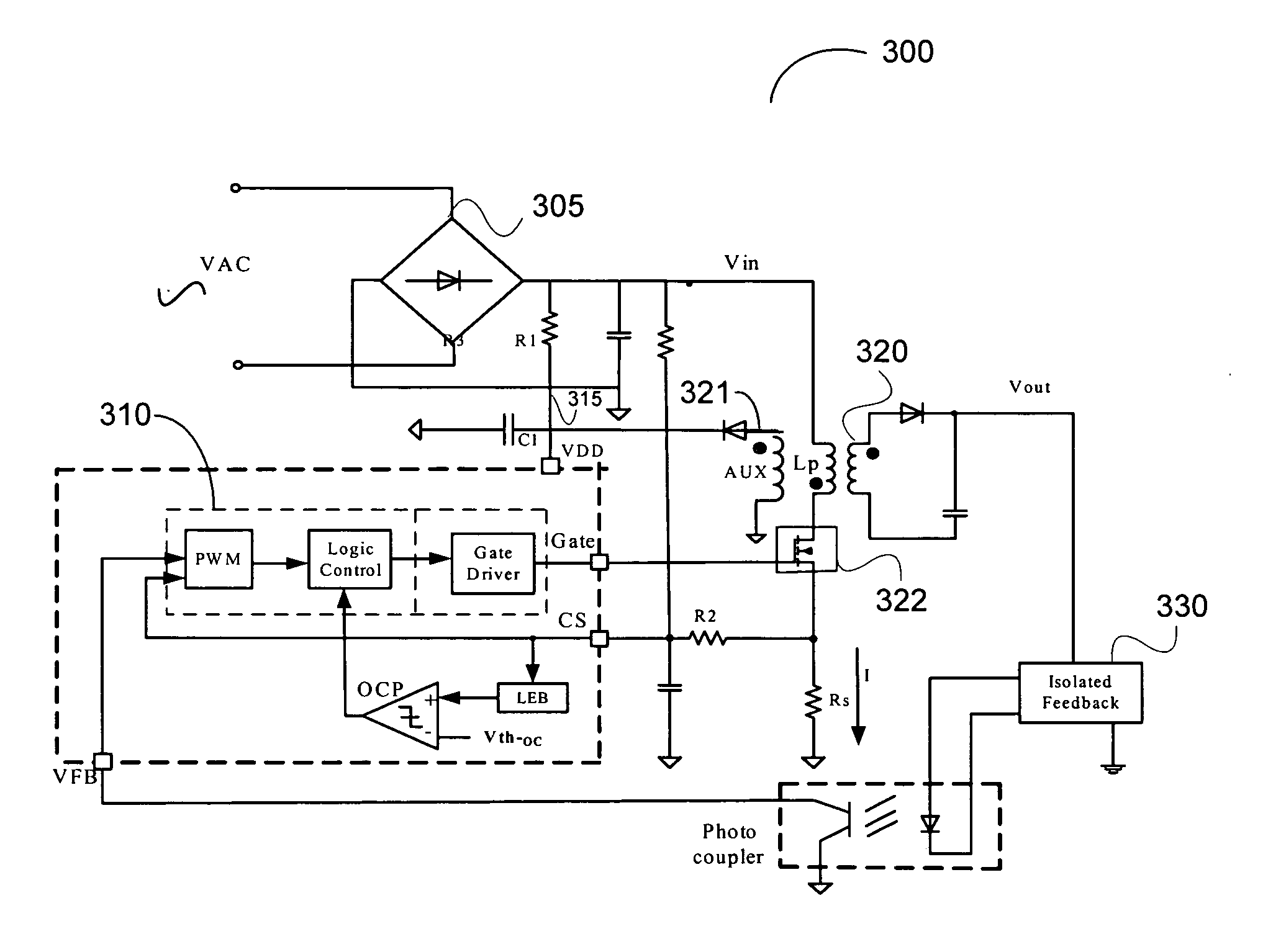
[0028]The present invention is related to integrated circuits. More specifically, the present invention can be applied to controllers used for switch mode power supply. According to various embodiments, the present invention provides various power control schemes to reduce standby power consumption and improves system efficiency. Merely by way of example, the present invention can be used in switch mode power conversion system including, among, other things, offline fly-back converters and forward converters. It is to be appreciated that the present invention has a broad range of applications.

[0029]As mentioned above, various techniques have been developed for efficient power systems. For example, conventional systems attempted to reduce switching power due to core loss of transformers and inductors in a power system and power loss due to the snubber. Typically, power losses are related with switching events. For example, high frequency switching usually results in high switching po...


PUM


Abstract

System and method for providing control for switch-mode power supply. According to an embodiment, the present invention provides a system for regulating a power converter. The system comprises a signal processing component that is configured to receive a first voltage and a second voltage, to process information associated with the first voltage and the second voltage, to determine a signal based on at least information associated with the first voltage and the second voltage, and to send the signal to a switch for a power converter. The switch is regulated based on at least information associated with the signal. The signal processing component is further configured to determine the signal to be associated a first mode, if the first voltage is higher than a first threshold.

Description

CROSS-REFERENCES TO RELATED APPLICATIONS[0001]This application claims priority to Chinese Patent Application No. 200610030188.X, filed Aug. 16, 2006, entitled “System and method for providing control for switch-mode power supply”, by inventors Jun Ye, Zhen Zhu, Shifeng Zhao, Zhiliang Chen, and Lieyi Fang, commonly assigned, incorporated by reference herein for all purposes.BACKGROUND OF THE INVENTION[0002]The present invention is related to integrated circuits. More specifically, the present invention can be applied to controllers used for switch mode power supply. According to various embodiments, the present invention provides various power control schemes to reduce standby power consumption and improves system efficiency. Merely by way of example, the present invention can be used in switch mode power conversion system including, among, other things, offline fly-back converters and forward converters. It is to be appreciated that the present invention has a broad range of applica...

Claims


Application Information

Patent Timeline
Patent Type & Authority Applications(United States)
IPC IPC(8): H02M3/24
CPCH02M3/33507Y02B70/16H02M2001/0032Y02B70/10H02M1/0032
Inventor YE, JUNZHU, ZHENZHAO, SHIFENGCHEN, ZHILIANGFANG, LIEYI
Owner ON BRIGHT ELECTRONICS SHANGHAI
Why Eureka
Try Eureka