Multiple use LED light fixture

a led light fixture and multi-use technology, applied in lighting applications, lighting support devices, lighting and heating apparatuses, etc., can solve the problems of low efficiency, high cost, and limitations of existing commercial fixtures, and achieve high quality light output, reduce failure risk, and energy-saving

Active Publication Date: 2010-01-21
ELECTRALED
View PDF9 Cites 150 Cited by
  • Summary
  • Abstract
  • Description
  • Claims
  • Application Information

AI Technical Summary

Benefits of technology

[0006]The present invention is directed to a light fixture that includes an LED light engine, which by design, is energy efficient and provides high quality light output. The inventive light fixture includes a rugged housing, a power supply that may be removeably mounted inside an external enclosure and an air flow passageway across the light engine whereby air flows along the passageway during operation of the light fixture. The rugged housing is of particular importance when the light fixture is configured for use in high-traffic commercial or industrial applications, such as warehouses, loading docks or shipping / receiving areas, where the light fixture is prone to be stricken by forklifts and other large objects. The light fixture includes several novel heat management features designed to thermally isolate the power supply and light engine in order to reduce the risk of failure and thereby increase the reliability of the light fixture.
[0008]According to another aspect of the invention, the light engine comprises a printed circuit board (PCB), a plurality of LED modules, and a lens extending outward from each module. Each module comprises a LED and a zener diode, which results in “bypass” circuitry to prevent catastrophic failure of the light engine. The light engine further comprises a heat transfer element, such as a thermal pad, positioned between the circuit board and the housing. The modules are divided into multiple groups, where each group includes multiple modules. Within each group, the modules are serially arrayed, and the groups are parallel to each other to facilitate current sharing from the power supply.
[0009]One aspect of using the light fixture of the present invention in a track light system including an elongated track is that many more light fixtures may be connected to the track than is possible with conventional incandescent or halogen light fixtures. The copper bus wire runs that are contained within a commercial track are predominantly limited to a maximum of twenty amps of current per circuit. The current required for an incandescent or halogen light fixture is much higher than the current required for an LED light fixture, thus many more LED light fixtures can be connected to the same track system. For example, a 120 watt incandescent light fixture will require about one amp of current, and a maximum of twenty incandescent light fixtures may be connected to a twenty amp circuit. However, a twenty watt LED light fixture will require about 0.167 amps of current, and a maximum of 120 LED light fixtures may be connected to a twenty amp track circuit. This example illustrates a five fold increase in the number of light fixtures that can be connected to a single track circuit. The total cost of the track system infrastructure is greatly reduced due to the requirement for fewer electrical feeds, breakers and light track circuits.
[0010]Another aspect of the inventive LED light fixture may easily replace or retrofit older incandescent track technology with the newer LED technology. The task simply requires unplugging the older light fixtures from the track and plugging in the newer LED light fixtures. Other advantages in addition to the reduced power required for the track lighting system include: less heat generated, less heat load on building cooling systems, longer operating life, reduced lighting maintenance costs, rugged impact resilient design, less breakage, environmentally friendly design with no mercury or lead being used in production and an aesthetically pleasing design.

Problems solved by technology

However, these existing commercial fixtures suffer from a variety of limitations, including but not limited to high cost, low efficiency, high power consumption and / or poor light output quality.
Other commercial fixtures may utilize LEDs, however, the heat generated by the LEDs during operation compromises the performance, lifetime and efficiency of these fixtures.
Thus, the overall appeal of existing commercial fixtures is limited, and will further erode as energy costs (and the related operating costs) continue to increase.

Method used


Image

  • Multiple use LED light fixture
  • Multiple use LED light fixture
  • Multiple use LED light fixture

Examples


first embodiment

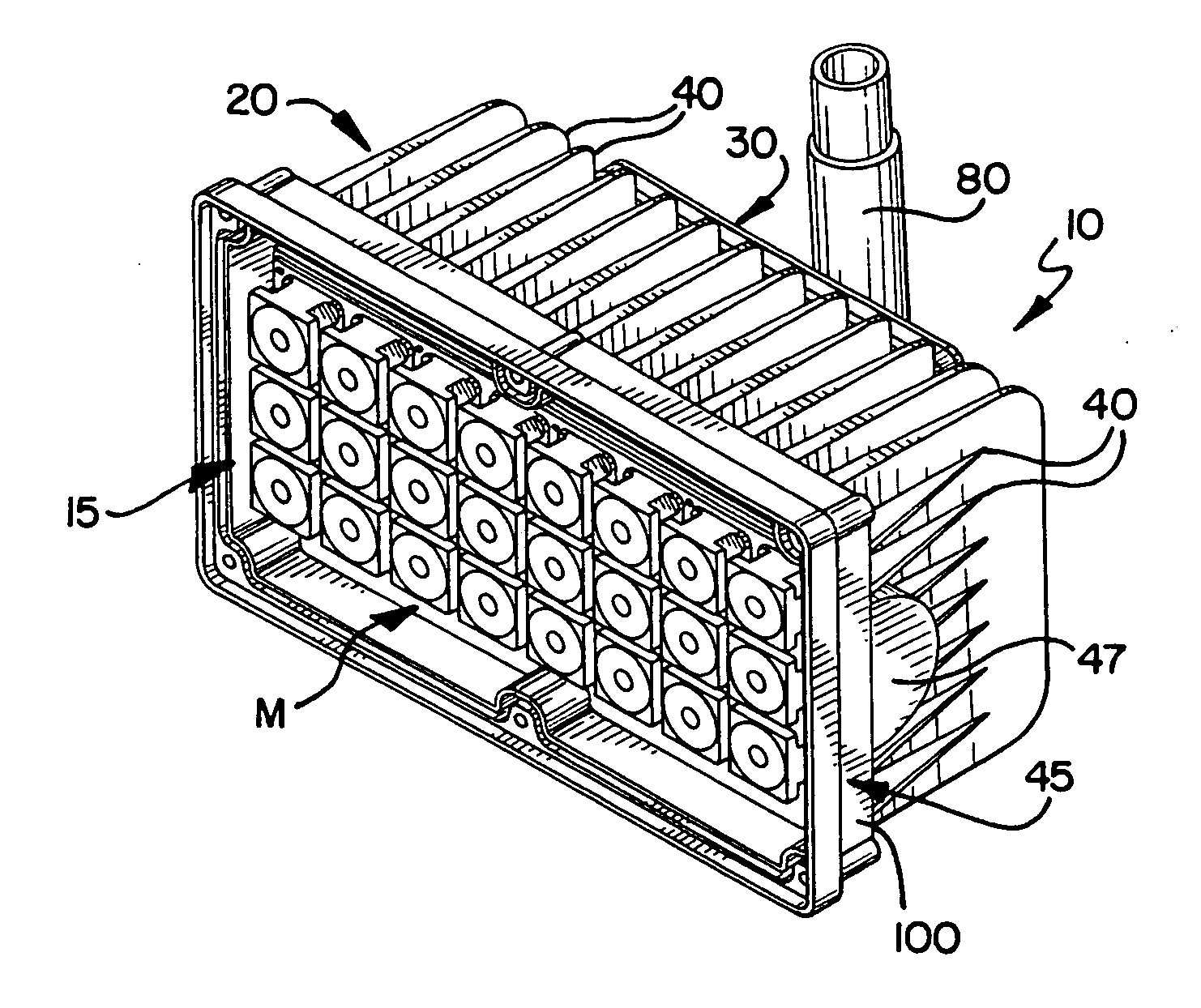
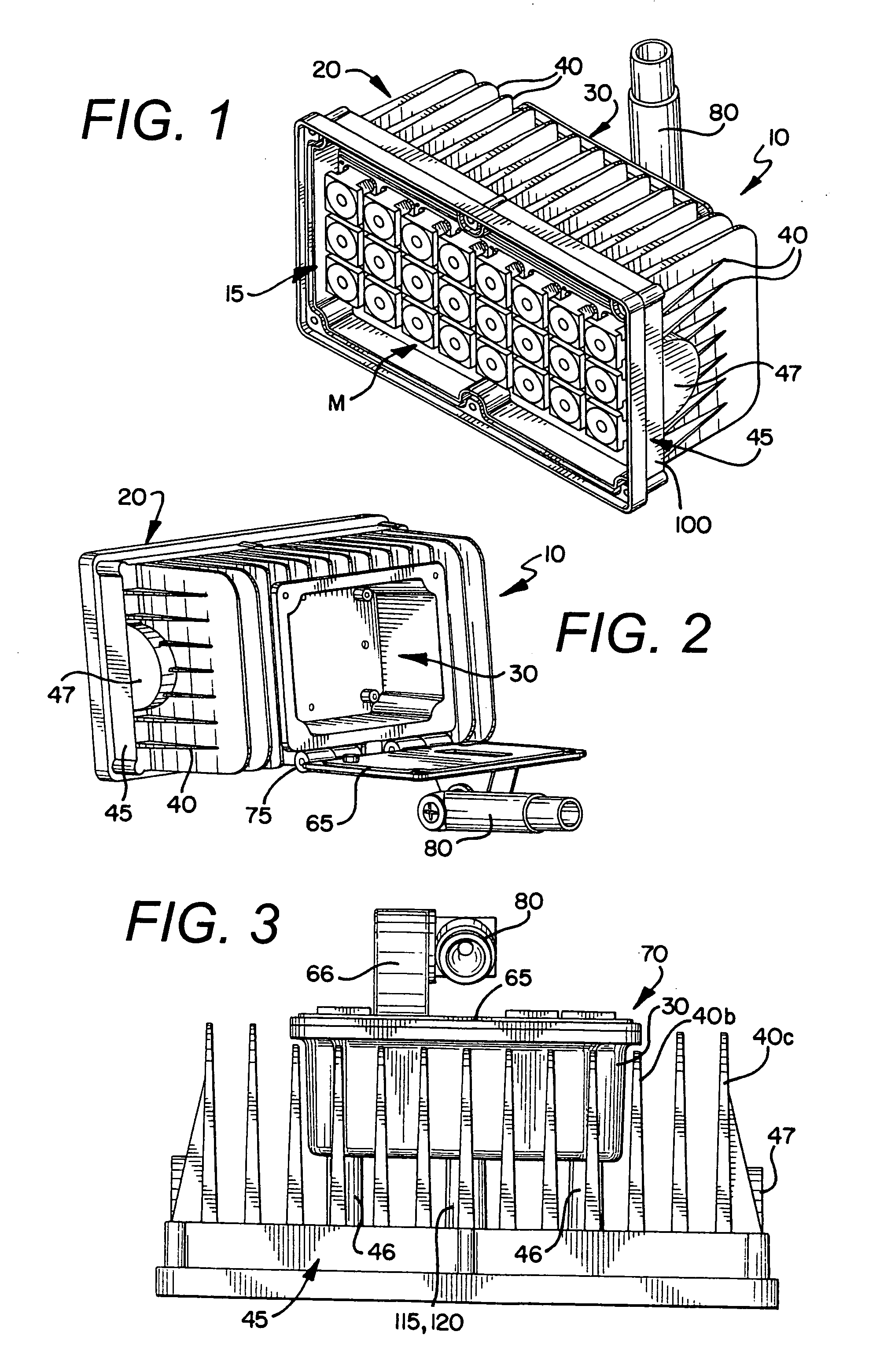
[0029]FIGS. 1-3 show a light fixture 10 of the present invention. The light fixture 10 includes a light engine assembly 15 featuring an arrangement of light emitting diodes (LEDs) 17, a rugged housing 20, an internal power supply 25 removably embedded within a box 30 of the housing 20, wherein the box 30 encloses the power supply 25 within the housing 20. This embodiment of the light fixture 10 is configured for use in commercial or industrial applications, such as loading docks or receiving areas. In these high-traffic areas, conventional light fixtures, which include an externally-mounted power supply, are prone to being struck by forklifts and other large objects. By positioning the power supply 25 within the housing 20, the inventive fixture 10 reduces both (a) the overall dimensions of the light fixture 10, and (b) the incidence of damage to the power supply 25. However, the embedded power supply 25 then becomes susceptible to failure from heat generated by the light engine 15....

second embodiment

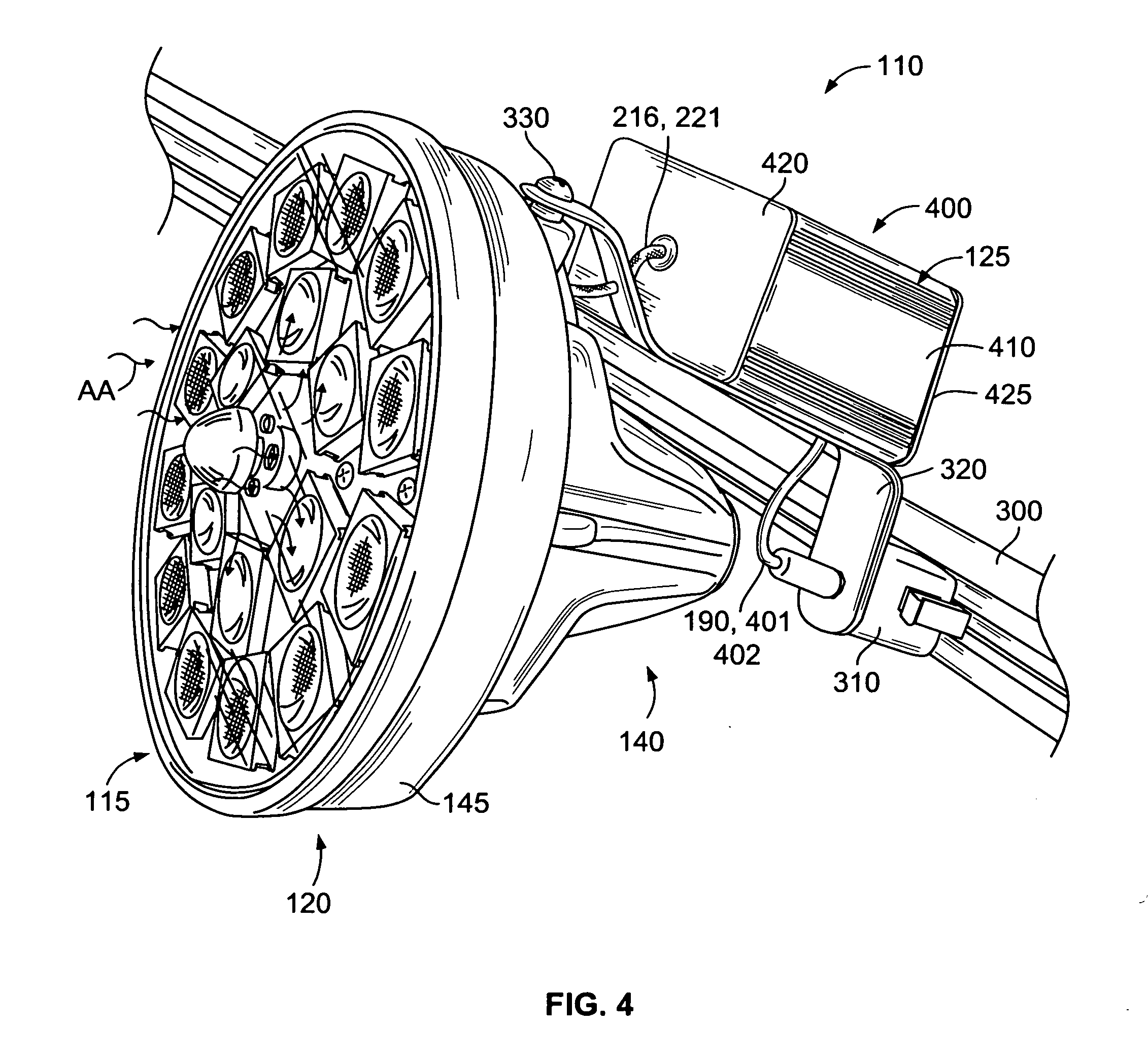
[0032]FIGS. 4-12 show a light fixture 110 of the present invention. The light fixture 110 includes a light engine assembly 115 featuring an arrangement of light emitting diodes (LEDs) 170, a rugged housing 120 and an external power supply 125 removably residing within an external enclosure box 400 to form a power module. This embodiment of the light fixture 110 is configured for use in track lighting systems but in place of conventional track lighting fixtures. This embodiment of the light fixture 110 also provides a rugged, low power, long life, high efficiency, high lumen output light source that may be used in commercial or industrial applications, such as loading docks or receiving areas. By positioning the power supply 125 either within the external enclosure box 400 or mounting it separately from the light fixture 110, the inventive fixture 110 reduces the incidence of damage to the power supply 125 and helps prevent failure from heat generated by the light engine 115. To incr...


PUM


Abstract

The invention provides a multi-use light fixture that includes a light engine, a rugged housing, and an external power supply removeably embedded within an optional external enclosure. The light fixture includes several novel heat management features designed to reduce the risk of failure and thereby increase the reliability of the light fixture. The light engine includes groups of light modules, each having a light emitting diode (LED) and a zener diode. The housing includes an internal gap defined between the a circuit board and the housing. The housing also includes an arrangement of external fins and vents that dissipate heat generated by the light engine. The lens cover includes a plurality of inlets to supply ambient air into the fixture. During operation, heat is generated by the light modules, namely the LEDs, and then is transferred along a first flow path through a main body portion of the housing and the fins for dissipation to ambient and a second air flow path whereby ambient air flows through the light engine to increase the performance and efficiency of the light engine.

Description

CROSS-REFERENCE TO RELATED APPLICATION[0001]The present application is a continuation-in-part of pending application U.S. Ser. No. 11 / 818,216, filed Jun. 13, 2007, and claims priority therefrom.FEDERALLY SPONSORED RESEARCH OR DEVELOPMENT[0002]N / ATECHNICAL FIELD[0003]The invention relates to a multi-use durable light fixture with improved thermal management properties to ensure reliable operation. More specifically, the light fixture includes a light engine featuring an arrangement of light emitting diodes (LEDs), a rugged high thermal performance housing featuring improved thermal performance through the use of an air flow passageway, and an external power supply removeably embedded within an optional external enclosure.BACKGROUND OF THE INVENTION[0004]Light fixtures suitable for commercial use, such as in or around buildings and commercial facilities, are typically designed to be durable since they can be struck or damaged during business operations. To provide this durability, exi...

Claims


Application Information

Patent Timeline
Patent Type & Authority Applications(United States)
IPC IPC(8): F21V1/00F21V29/15
CPCF21V15/01F21V21/30F21V23/026F21V29/004F21V29/225F21W2131/10F21V29/763F21Y2101/02F21K9/30F21K9/50F21V29/2206F21V29/15F21V29/75F21W2131/40F21Y2115/10F21V29/74F21V19/003F21K9/69F21V23/023F21W2131/402F21V29/767F21V29/773F21S2/005F21V23/02F21V31/03
Inventor THOMAS, JAMESGATESMAN, GARYLYND, DAVIDMOSIER, JIMWARNER, BRYAN T.
Owner ELECTRALED
Why Eureka
Try Eureka