Thermostat display system providing animated icons

a technology of display system and thermostat, which is applied in the field of digital thermostats, can solve the problems of several consumer complaints, display does not provide any indication of the activeness of heating or cooling equipment in the home, and the overall user experience of interfacing with such a digital thermostat has not kept pace, so as to achieve energy-saving effects

Inactive Publication Date: 2008-11-25
RANCO OF DELAWARE
View PDF23 Cites 147 Cited by
  • Summary
  • Abstract
  • Description
  • Claims
  • Application Information

AI Technical Summary

Benefits of technology

[0012]The present invention provides a new and improved digital thermostat. More particularly, the present invention provides a new and improved digital thermostat having a display system that provides heating and cooling system operating information to the user in a non-intrusive and non-annoying manner. Even more particularly, the present invention provides a new and improved digital thermostat having a display system that provides heating and cooling system operating information to the user in an energy efficient and intuitive manner.
[0013]In one embodiment of the present invention, the display system for a digital thermostat provides animated icons on the user display of the digital thermostat. Such animated icons on the user display of the digital thermostat eliminates the need for the end user to modify the electronics of the digital thermostat by providing an intuitive interface to indicate activity of the heating and / or cooling equipment. In a preferred embodiment of the present invention, the animated icons are provided on a dot matrix liquid crystal display (LCD). Such animated icons on the LCD display do not utilize a significant amount of energy compared with the previous LED indicators, greatly enhancing the battery life of battery powered thermostats or thermostat interfaces.
[0015]One embodiment of the present invention provides both LED and animated LCD indication of the operational status of the heating and / or cooling equipment. In such an embodiment, the thermostat preferably provides the user with the capability of disabling the LED indicators so as to not be annoying and / or distracting to the user.

Problems solved by technology

While the advances that are being included in modern digital thermostats greatly enhance the users' comfort level and minimize the energy usage, the overall user experience interfacing with such a digital thermostat has not kept pace.
Specifically, while such digital thermostats typically provide some form of user interface screen from which information is conveyed to the consumer, and from which the consumer may program the operation of the thermostat, such displays do not provide any indication that the heating or cooling equipment in the home is active.
However, such LED indicators have led to several consumer complaints, and in some cases, reduction in performance of the thermostat itself.
Unfortunately, many consumers have complained that such an LED indication is annoying, distracting, and unwanted in several situations.
Another is when the thermostat is installed in a bedroom or other area where such a bright LED indicator would prove to be annoying.
The user is then forced to repeatedly removing the tape to determine the operational status, and replacing the tape when such LED indication would prove annoying or distracting.
In other thermostats, for example, battery powered thermostats or remote home control units, the inclusion of LED indicators reduces the useful battery life and therefore operational readiness of the thermostat itself.
As such, manufacturers typically do not include LED indicators on such battery powered devices.
Because of the extra power demand from these added indicators, however, this typically results in the batteries of the thermostat having a shorter life.
However, hardwiring an indicator directly to the control line of the thermostat may cause spurious operation of the heating and / or cooling system due to the added component in the control line.

Method used


Image

  • Thermostat display system providing animated icons
  • Thermostat display system providing animated icons
  • Thermostat display system providing animated icons

Examples


Embodiment Construction

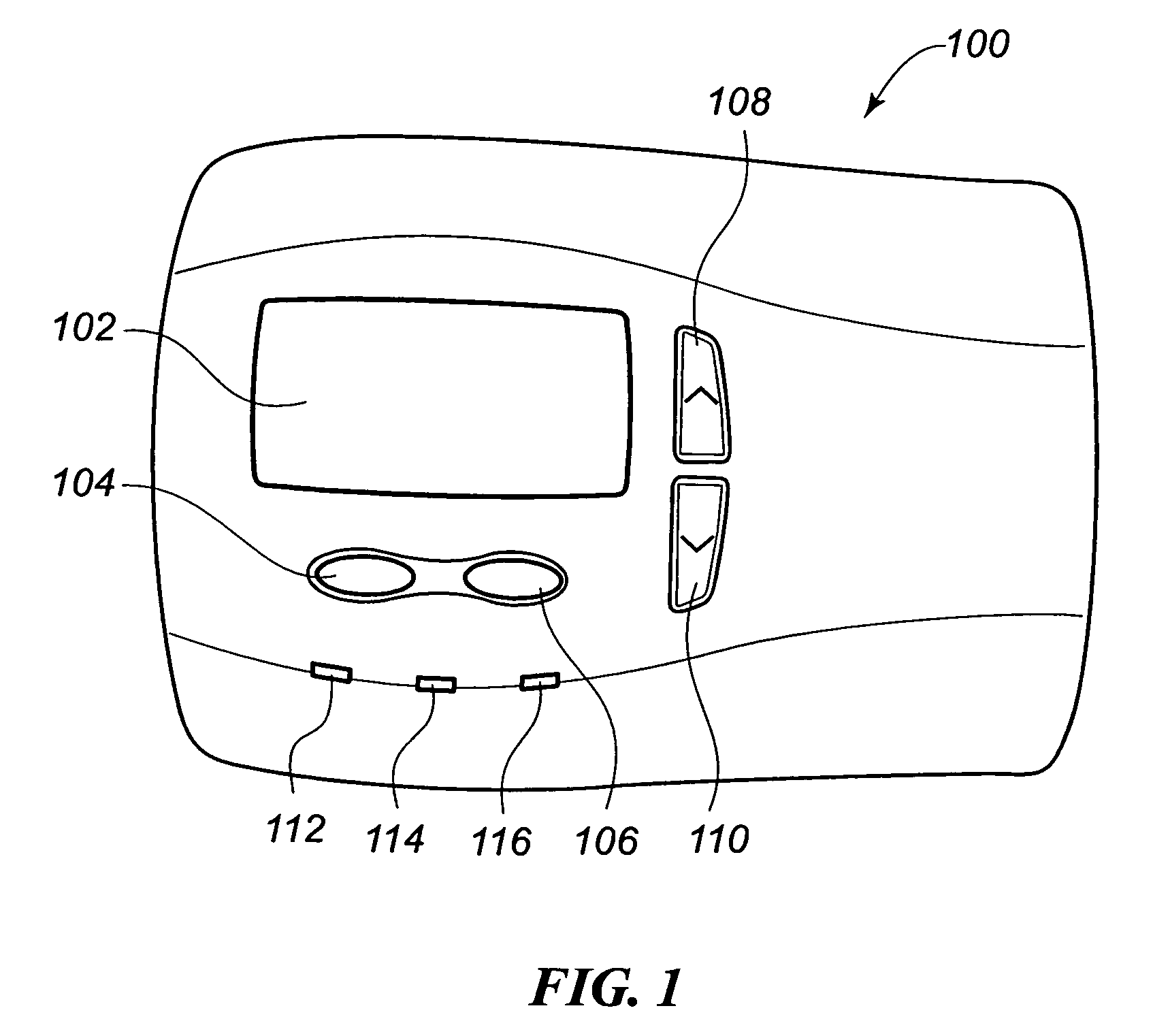
[0022]An embodiment of a thermostat constructed in accordance with the teachings of the present invention that incorporates the display system of the present invention is illustrated in FIG. 1. As with many thermostats, an internal temperature sensor that is monitored by the internal processor is included within the thermostat 100. As may be seen from this FIG. 1, this embodiment of the thermostat 100 includes a user display 102 on which is displayed programmatic, system, and ambient information regarding the operation of the HVAC system. This user display 102 may take various forms as are well-known in the art, and in a preferred embodiment is a dot matrix LCD display. With such a display 102, the consumer may activate various programmatic and control functions via a pair of soft keys 104, 106. The functionality executed by these soft keys 104, 106 varies dependent upon the programmatic state in which the thermostat 100 is at the time one of the soft keys 104, 106 is depressed. The...


PUM


Abstract

A visual display system and method for a digital thermostat having a user display screen to provide operational status information of the heating and / or cooling equipment controlled by the thermostat is provided. This visual display system utilizes animated icons to show operational status of the heating and / or cooling equipment. Static icons may also be used in one embodiment to indicate the current mode of the thermostat. Animated icons for the heating system, the cooling system, and fan operation are provided. The illusion of animation is provided by overwriting or replacing a displayed image with another image at a predetermined frequency. This predetermined frequency may be changed programmatically, and varied to provide different visual effects.

Description

FIELD OF THE INVENTION[0001]The present invention relates generally to digital thermostats, and more particularly to a display system for a digital thermostat to convey system operating information to a user.BACKGROUND OF THE INVENTION[0002]Occupants of dwellings and commercial structures have long benefited from the inclusion of a heating, ventilating, and air conditioning (HVAC) system that regulates the temperature and humidity within the dwelling or structure. Traditionally, the thermostat that controlled this temperature regulating equipment was a fairly simple electromechanical device that was simply wired to a heating device and / or to a cooling device. Once installed, the user need only move a selector switch between heating and cooling to designate which equipment was desired to be operated, move a selector switch between run and auto for a fan control, and rotate a dial to a desired set point temperature. No other user interface to the thermostat was needed or available, an...

Claims


Application Information

Patent Timeline
Patent Type & Authority Patents(United States)
IPC IPC(8): B64D13/00F24D19/10G05B15/00
CPCF23N5/022G05D23/1902F23N2041/02F23N2025/12F23N2225/12F23N2241/02F23N5/20G05B19/04
Inventor CHAPMAN, JR., JOHN GILMANBURT, ROBERTGRAY, TONY
Owner RANCO OF DELAWARE
Why Eureka
Try Eureka