Intelligent drive circuit for a light emitting diode (LED) light engine

a technology of intelligent drive circuit and light-emitting diodes, which is applied in the direction of electric variable regulation, process and machine control, instruments, etc., can solve the problems of accelerating the degradation of leds, consuming significantly more energy than needed, and shortening the operating life of leds, so as to achieve more energy efficiency and prolong the operating li

Active Publication Date: 2006-02-09
DIALIGHT CORP
View PDF5 Cites 151 Cited by
  • Summary
  • Abstract
  • Description
  • Claims
  • Application Information

AI Technical Summary

Benefits of technology

[0009] A more specific object of the present invention is to provide a novel control for driving an LED light engine that is more energy efficient and leads to a longer operating life for an LED, by not initially driving an LED with a higher drive current than needed for a desired light output. The novel control of the present invention intelligently varies a drive current supplied to an LED light engine to drive an LED light engine to output a constant desired light output throughout its life.
[0010] Further, another object of the present invention is to provide a novel system and method for providing an indication when an LED light output has degraded below a certain point.

Problems solved by technology

That is, when the LED initially is driven with a drive current 30% higher than that necessary to achieve a desired light output, the LED will consume significantly more energy than needed.
Also, driving LEDs with more power accelerates degradation of the LEDs and shortens their operating life, thereby mitigating another benefit of using LEDs.

Method used


Image

  • Intelligent drive circuit for a light emitting diode (LED) light engine
  • Intelligent drive circuit for a light emitting diode (LED) light engine
  • Intelligent drive circuit for a light emitting diode (LED) light engine

Examples


Embodiment Construction

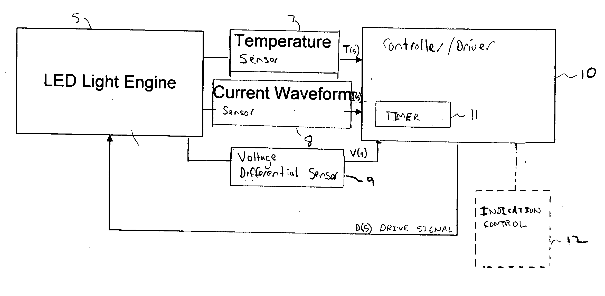
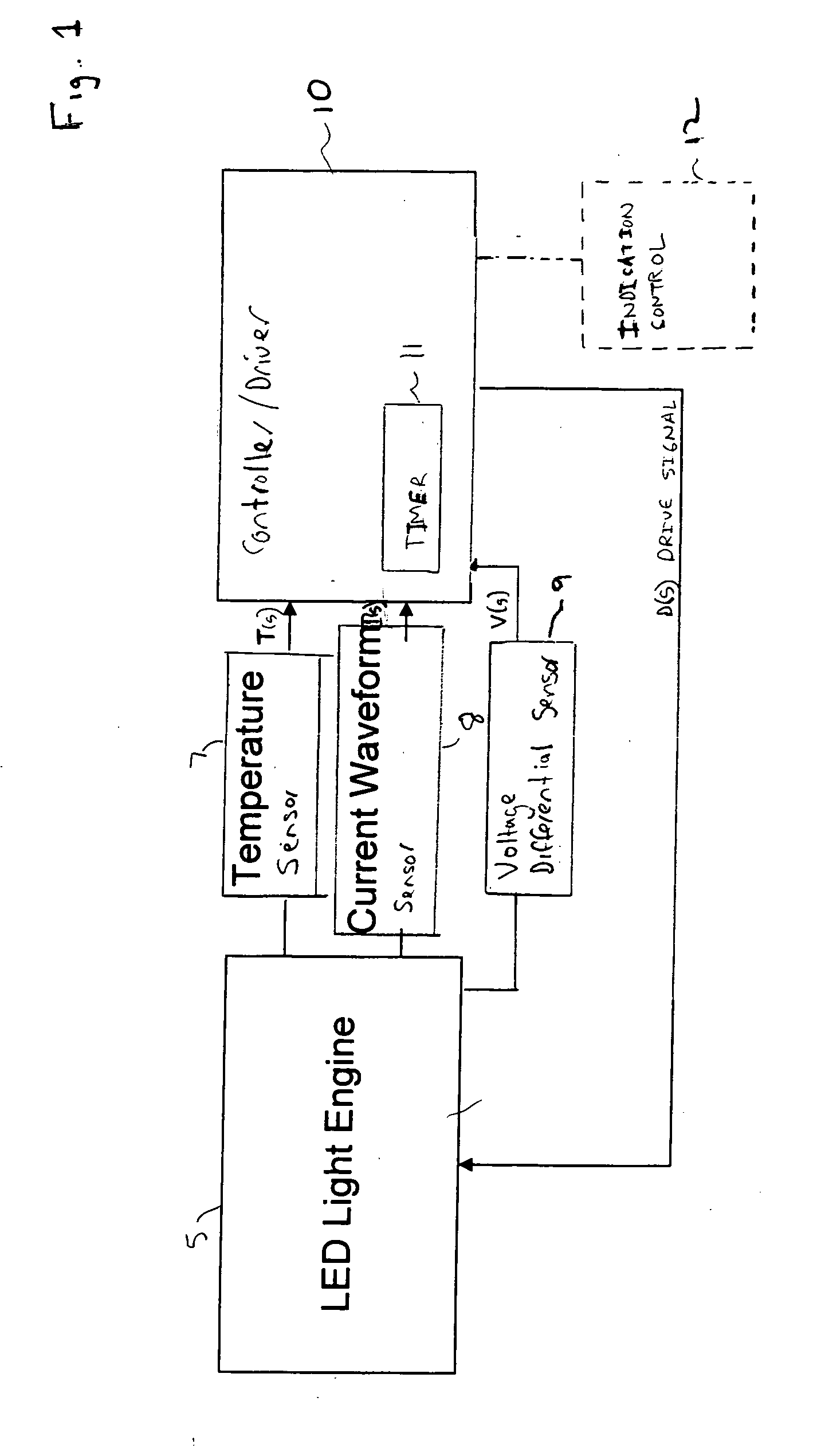
[0017] Referring now to the drawings, wherein like reference numerals designate identical or corresponding parts throughout the several views, and more particularly to FIG. 1 thereof, an overview of a control system for driving an LED light engine 5 that contains LEDs, or at least one LED, for illumination is shown.

[0018] In FIG. 1, a temperature sensor 7 senses a temperature at the LED light engine 5, and outputs a sensed temperature signal T(s) based on the sensed temperature. A current waveform sensor 8 senses a drive current of the LED light engine 5 and outputs a corresponding sensed current waveform signal I(s). A voltage differential sensor 9 senses a voltage differential across the LEDs of the LED light engine 5 and outputs a corresponding voltage differential signal V(s).

[0019] A controller / driver 10 receives the sensed temperature signal T(s), the sensed current waveform signal I(s), and the sensed voltage differential signal V(s). The controller / driver 10 also includes ...


PUM


Abstract

A controller for controlling a light emitting diode (LED) light engine. The controller includes a temperature sensor configured to sensor temperature at the LED light engine. A current sensor senses a drive current of the LED light engine. A voltage differential sensor senses a voltage differential across LEDs of the LED light engine. A timer monitors a time of operation of the LED light engine. Further, a control device controls the drive current to the LED light engine based on the sensed temperature, the sensed drive current, the sensed voltage differential, and the monitored time of operation. Further, the control device outputs an indication of intensity degradation of an LED, and if the intensity degradation exceeds a predetermined threshold the control can output an indication of such to a user, so that the user can be apprised that the LED needs to be changed.

Description

BACKGROUND OF THE INVENTION [0001] 1. Field of the Invention [0002] The present invention is directed to a control device for a light emitting diode (LED) light engine, and more particularly to a control device that can efficiently control a drive current provided to the LED light engine. [0003] 2. Description of the Background Art [0004] Light engines including LEDs as light sources are well known. An LED as a light source degrades over time, in contrast to an incandescent lamp that operates at a given light output and then at a specific time bums out and ceases to operate at all. [0005] One manner to compensate for the long term degradation of light output by an LED is to initially drive the LED with a much higher driving current than is necessary for a desired light output. For example, an LED can be initially driven with a drive current at, for example, 30% higher than required for a desired light output. In that manner when the LED slowly degrades over time, the light output fr...

Claims


Application Information

Patent Timeline
Patent Type & Authority Applications(United States)
IPC IPC(8): H05B37/02H01L33/00H05B44/00
CPCH05B33/0818H05B33/0893H05B33/0854H05B33/0851H05B45/58H05B47/20H05B45/18H05B45/14Y02B20/40
Inventor YOUNG, GARRETT
Owner DIALIGHT CORP
Why Eureka
Try Eureka