Current-mode direct-drive inverter

a direct-drive inverter and current-mode technology, applied in the direction of electric variable regulation, process and machine control, instruments, etc., can solve the problems of gas discharge lamps having a negative resistance characteristic, difficult to strike the lamp and regulate the lamp current without costly and complex circuits,

Inactive Publication Date: 2005-07-28
POLARIS POWERLED TECH LLC
View PDF99 Cites 69 Cited by
  • Summary
  • Abstract
  • Description
  • Claims
  • Application Information

AI Technical Summary

Benefits of technology

[0007] The present invention proposes an efficient and flexible current-mode driver for delivering power to one or more light sources in a backlight system. Backlight is needed to illuminate a screen to make a visible display in liquid crystal display (LCD) applications, such as a LCD television, a desk top monitor, an automotive display, a notebook computer, a tablet computer, etc. In one embodiment, fluorescent lamps are used as the light sources in the backlight system, and a current-mode inverter generates a regulated current to drive the fluorescent lamps. The regulated current helps to generate a stable light output and to maintain a long operating life for the fluorescent lamps.
[0008] The current-mode inverter advantageously operates in a single continuous operating mode for both striking and regulating power to a lamp, such as a cold cathode fluorescent lamp (CCFL). In other words, no dedicated circuits or algorithms are needed to strike the lamp. The single continuous mode of operation simplifies the number of functions supported by a current-mode controller in the current-mode inverter. In one embodiment, the current-mode controller has less than half as many functions as a voltage-mode controller and can be implemented using approximately half as much chip area. In addition, the current-mode inverter has direct control over the lamp current, thus eliminating the need for tuning or other accommodations to account for different lamps or aging of lamps.
[0011] The relatively high frequency operation of the first switching stage (or power switching stage) advantageously reduces size of components (e.g., the transformer). In one embodiment, the first switching stage operates in a frequency range of 100 kilohertz to 4 Megahertz. In one application, the first switching stage operates at approximately 2 Megahertz. The relatively low frequency operation of the second switching stage (or polarity switching stage) advantageously improves efficiency (e.g., by reducing switching loss or by reducing crest factor in load current). In one embodiment, the second switching stage operates in a frequency range of 100 hertz to 4 kilohertz. In one application, the second switching stage operates at approximately 400 hertz.
[0015] In one embodiment, a current-mode driver delivers power to a plurality of light sources in a backlight system by providing a regulated current to a network of semiconductor switches coupled in series and the light sources coupled across the respective semiconductor switches. Each of the semiconductor switches individually closes to isolate its associated light source from the regulated current or selectively opens to allow the associated load to conduct the regulated current. In one embodiment, the network of semiconductor switches uses a time sharing technique to selectively provide the regulated current to different portions of an array of light emitting diodes (LEDs) used to backlight a LCD. For example, a string of series-connected LEDs corresponding to a row in the array is coupled across each semiconductor switch. The semiconductor switches periodically close in sequential order to minimize backlight in portions of the LCD that is currently updating its image. The time sharing technique advantageously allows a single current source to power banks (or arrays) of series-coupled light sources.

Problems solved by technology

The voltage regulation technique makes striking the lamp and regulating the lamp current difficult to achieve without costly and complex circuitry.
The starting algorithm usually runs at a higher frequency and uses strike detection circuits that complicate the lamp driver design.
Furthermore, gas discharge lamps have a negative resistance characteristic, and the lamp driver typically needs some degree of resonance to achieve sufficient high impedance for smooth operation after striking the lamp.

Method used


Image

  • Current-mode direct-drive inverter
  • Current-mode direct-drive inverter
  • Current-mode direct-drive inverter

Examples


Embodiment Construction

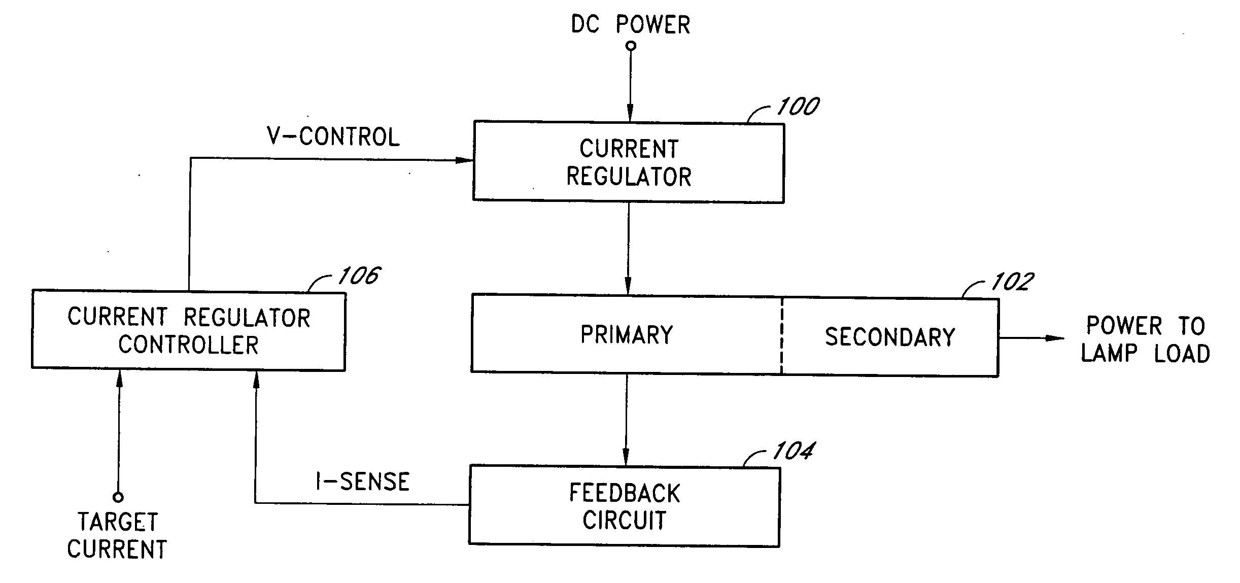
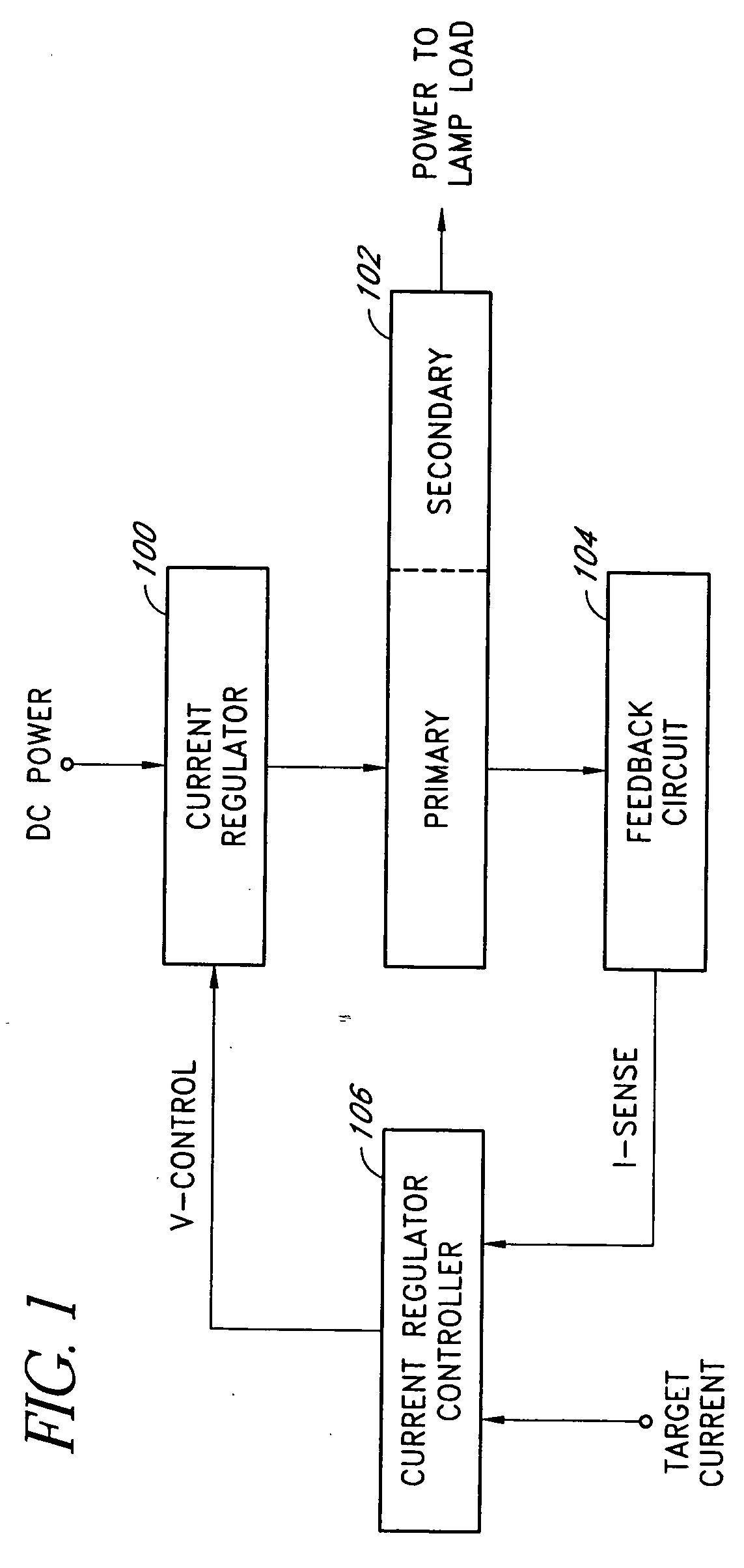
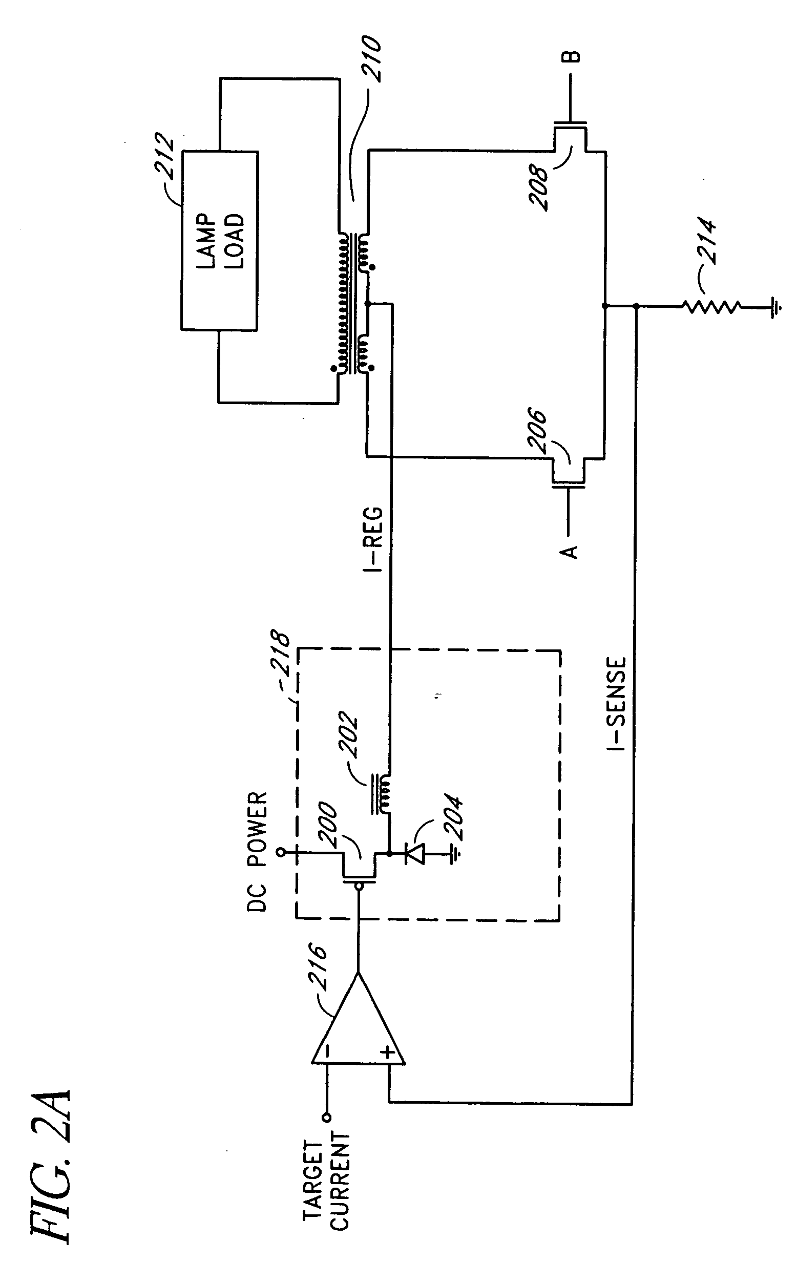
[0028] Embodiments of the present invention will be described hereinafter with reference to the drawings. FIG. 1 is a simplified block diagram of one embodiment of a current-mode inverter. The current-mode inverter includes an input current regulator 100, a polarity-switching and transformer network (or polarity reversing stage) 102, a feedback circuit 104, and a current regulator controller 106. The input current regulator 100 accepts a DC power source (e.g., a regulated or unregulated DC voltage) and generates a regulated current for the polarity-switching and transformer network 102. The polarity-switching and transformer network 102 includes semiconductor switches, such as metal-oxide-semiconductor field-effect-transistors (MOSFETs), directly coupled to a primary winding of a closely-coupled transformer. The semiconductor switches are controlled by a controller (e.g., a pulse width modulator) to periodically couple the regulated current through the primary winding in alternate s...


PUM


Abstract

An efficient and flexible current-mode driver delivers power to one or more light sources in a backlight system. In one application, the current-mode driver is configured as an inverter with an input current regulator, a non-resonant polarity-switching network, and a closely-coupled output transformer. The input current regulator can output a regulated current source in a variety of programmable wave shapes. The current-mode driver may further include a rectifier circuit and a second polarity-switching network between the closely-coupled output transformer and a lamp load. In another application, the current-mode driver delivers power to a plurality of light sources in substantially one polarity by providing a regulated current to a network of time-sharing semiconductor switches coupled in series with different light sources coupled across each semiconductor switch.

Description

CLAIM FOR PRIORITY [0001] This application claims the benefit of priority under 35 U.S.C. § 119(e) of U.S. Provisional Application No. 60 / 530,025, filed on Dec. 16, 2003 and entitled “Current-Mode Driver for CCFL,” the entirety of which is incorporated herein by reference. RELATED APPLICATIONS [0002] Applicant's copending U.S. Patent Applications entitled “Inverter with Two Switching Stages for Driving Lamp,”“Lamp Current Control Using Profile Synthesizer,” and “Method and Apparatus to Drive LED Arrays Using Time Sharing Technique,” filed on the same day as this application, are hereby incorporated by reference herein.BACKGROUND OF THE INVENTION [0003] 1. Field of the Invention [0004] The present invention relates to a current-mode driver for powering different light sources in a backlight system. [0005] 2. Description of the Related Art [0006] Inverter controllers for driving lamps typically regulate the voltage across each lamp and any series-connected ballast capacitor or inducto...

Claims


Application Information

Patent Timeline
Patent Type & Authority Applications(United States)
IPC IPC(8): H01LH05B37/02H05B39/00H05B41/16H05B41/24H05B41/282H05B44/00
CPCH05B33/0815H05B33/083Y10S315/04Y02B20/347H05B41/2828H05B45/48Y02B20/30H05B45/39H05B45/382
Inventor BALL, NEWTON E.
Owner POLARIS POWERLED TECH LLC
Why Eureka
Try Eureka