Ornamental container for containing refrangible/reflexible object

a container and ornamental technology, applied in the field of ornaments, can solve problems such as object interferen

Inactive Publication Date: 2010-07-22
CALIBER MULTIMEDIA TECH & TRADING
View PDF13 Cites 9 Cited by
  • Summary
  • Abstract
  • Description
  • Claims
  • Application Information

AI Technical Summary

Benefits of technology

[0009]The foregoing objectives of the present invention are attained by the ornamental container composed of a transparent bottle, a bottle cap, and an illuminating unit. The transparent bottle having an opening formed at a top side thereof. A refrangible / reflexible object is put into the transparent bottle. The bottle cap is mounted to the top side of the transparent bottle to seal the opening. The illuminating unit includes a power source, a circuit, a push switch, and a light source. The power source can provide electric energy for the circuit. The push switch can be controlled to switch on or off the light source. The bottle cap is formed of a hollow barrel and a cover member. The hollow barrel has a through hole running through a bottom side thereof. The cover member is mounted onto the hollow barrel in such a way that a chamber is formed between the hollow barrel and the cover member. When the cover member is pressed by an external force, at least one part of the cover member is deformed or moved downward. The illuminating unit is mounted inside the chamber. The light generated by the light source passes through the through hole to be shone downwardly. The push switch is located below the cover member and can be forced by the downward deformation or movement of the cover member to activate or deactivate the light source. Therefore, the push switch is hidden in the bottle cap to keep the delicacy of the ornamental container and the refrangible / reflexible object inside the ornamental container looks dazzling.

Problems solved by technology

However, the light sources in some of them each may interference the object in location; the switches in some of them are located outside the bottle each to be inaesthetic.

Method used


Image

  • Ornamental container for containing refrangible/reflexible object
  • Ornamental container for containing refrangible/reflexible object
  • Ornamental container for containing refrangible/reflexible object

Examples


Embodiment Construction

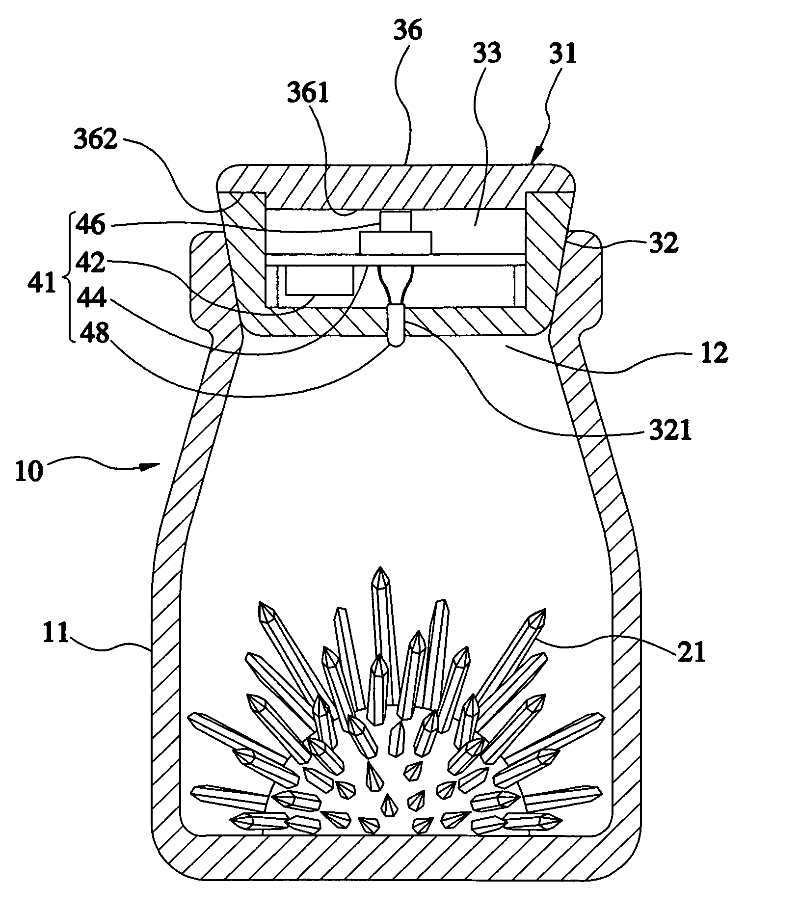
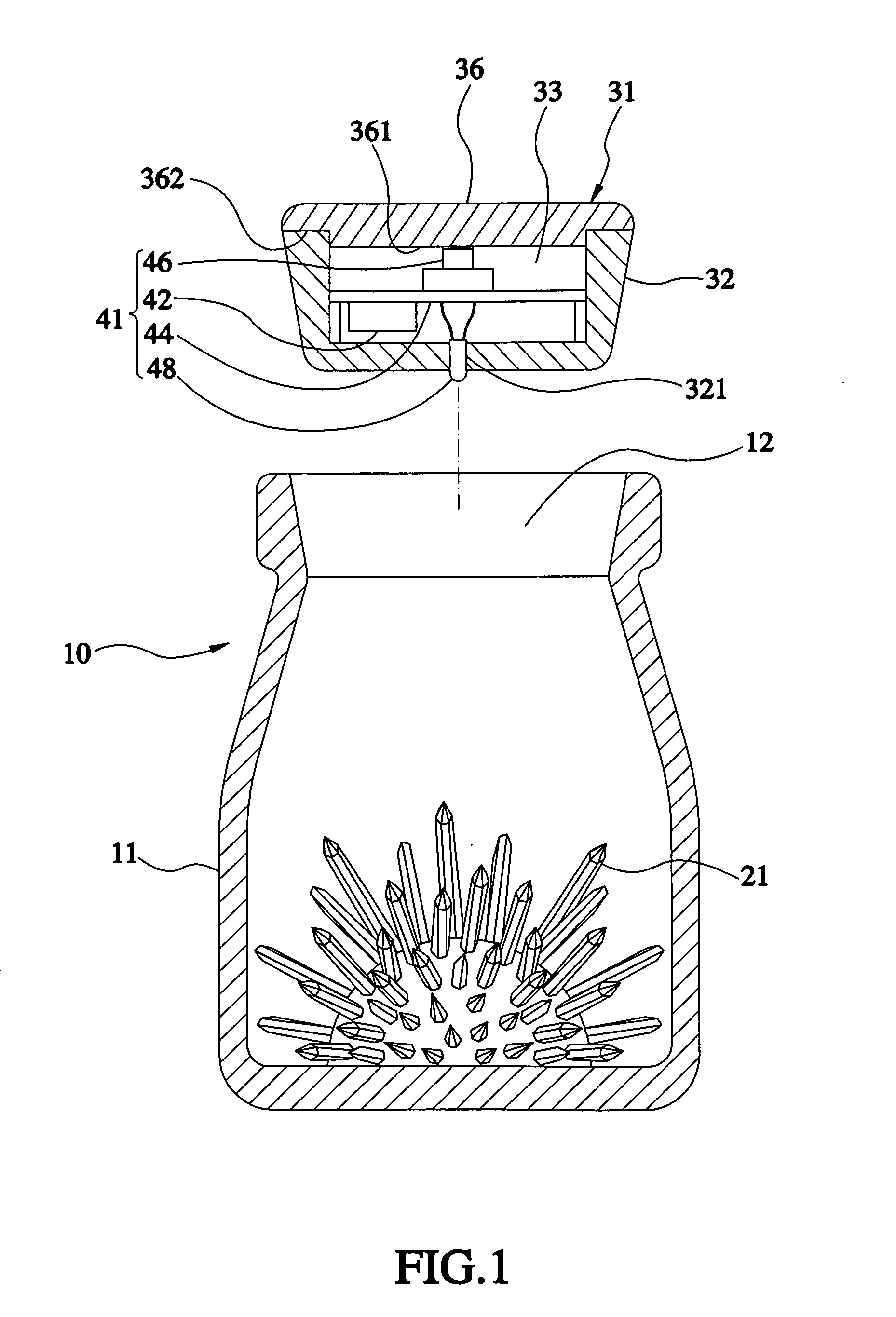
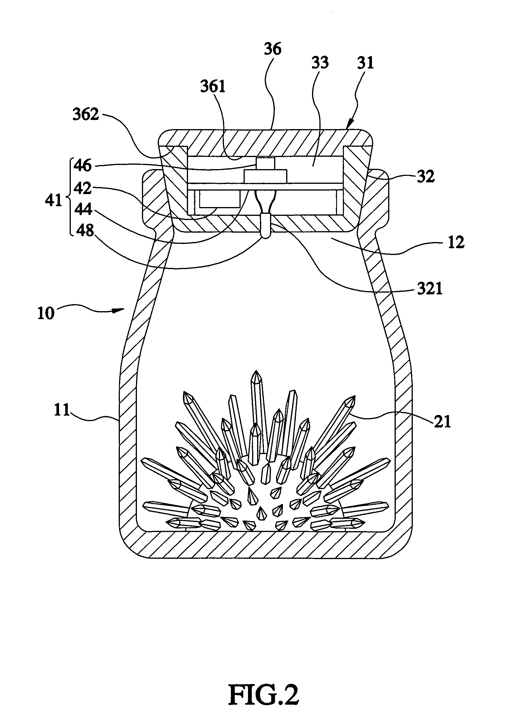
[0014]Referring to FIGS. 1-2, an ornamental container 10 constructed according to a first preferred embodiment of the present invention is composed of a transparent bottle 11, a bottle cap 31, and an illuminating unit 41.

[0015]The transparent bottle 11 includes an opening 12 formed on a top side thereof, for accommodating a refrangible / reflexible object 21. The refrangible / reflexible object 21 is a crystal, crystallization, glass, sequin, or lens, and put inside the transparent container 11.

[0016]The bottle cap 31 is mounted to the opening 12.

[0017]The illuminating unit 41 includes a power source 42, a circuit 44, a push switch 46, and a light source 48. The power source 42 can provide electric energy for the circuit 44. The light source 48 can be controlled by the push switch 46 for activation or deactivation. In this embodiment of the present invention, the power source is a battery and the light source is a light emitting diode (LED), which can be controlled by the circuit 44 to ...


PUM


Abstract

An ornamental container includes a transparent bottle, a bottle cap, and an illuminating unit. The transparent bottle accommodates a refrangible/reflexible object. The bottle cap is formed of a hollow barrel and a cover member. The hollow barrel has a through hole running through a bottom side thereof. When the cover member is pressed, at least one part of the cover member is deformed or moved downwardly. The illuminating unit includes a power source, a circuit, a push switch, and a light source. The light generated by the light source passes through the through hole to be shone downwardly. The push switch is located below the cover member and can be forced by the downward deformation or movement of the cover member to activate or deactivate the light source. Therefore, the push switch is hidden to keep the delicacy of the ornamental container and the refrangible/reflexible object looks dazzling.

Description

BACKGROUND OF THE INVENTION[0001]1. Field of the Invention[0002]The present invention relates generally to ornaments, and more particularly, to an ornamental container containing a refrangible / reflexible object.[0003]2. Description of the Related Art[0004]A conventional ornament e.g. a transparent bottle, is usually contained with a doll, colored sands, or a miniature object, like sailboat, table, chair, plants, etc., for people's appreciation.[0005]When an object, like glass or crystal, which can refract the light, or an object, like sequin or mirror, which can reflect the light is put into the transparent bottle, and then the light passes through the bottle, the light is reflected or refracted by the object in such a way that people feel dazzling while watching the bottle. Thus, the bottle has good ornamental effect.[0006]Recently, some transparent bottles, each of which is provided with a light source shone on an object located therein to look dazzling on the whole, were presente...

Claims


Application Information

Patent Timeline
Patent Type & Authority Applications(United States)
IPC IPC(8): F21V33/00B65D85/00
CPCB65D51/248
Inventor CHANG, CHUAN-YING
Owner CALIBER MULTIMEDIA TECH & TRADING
Why Eureka
Try Eureka