
Ridgeline cable drive electric energy storage system

a technology of electric energy storage and ridgeline cable, which is applied in the direction of electrical storage system, rope railway, machine/engine, etc., can solve the problems of increasing complexity, flyingwheel storage system limitations of less than 10 megawatts, and capacitive storage systems on reasonable scale only provide between 1-10 megawatts of capability, etc., and achieve high efficiency.

Active Publication Date: 2017-10-05
ADVANCED RAIL ENERGY STORAGE
View PDF4 Cites 12 Cited by
  • Summary
  • Abstract
  • Description
  • Claims
  • Application Information

AI Technical Summary

Benefits of technology

The invention is a highly effective energy storage system that can store and generate electricity. It uses a power controller and a module that has tracks and a winch set to move a mass between two storage locations. The module can either charge or discharge, depending on the needs of the system. It is designed to efficiently store and generate energy, making it useful for utility-scale applications.

Problems solved by technology

This issue is becoming more complicated with the addition of alternative energy generation sources such as wind power and solar power, which have inherent issues with consistency of power production.
Similarly, capacitive storage systems on reasonable scale only provide between 1-10 megawatts of capability.
Flywheel storage systems are also typically limited to less than 10 megawatts due to physical size and structural materials constraints.
Mechanical lifting devices are limited in their height to a few hundred feet and therefore require large amounts of mass to store a significant amount of electric energy.
This results in a very large cost, making these devices expensive and uneconomical.
The energy losses are typically greater than 20% of the amount stored and the difficulties in permitting, constructing and operating makes pumped storage hydro difficult to implement.
It can take more than a decade to construct such a system.
However, such systems are designed to operate on steep conventional rail grades with larger storage yards available at each end of the system.
In certain geographic areas those steep conventional grade features may not be available.

Method used


Image

  • Ridgeline cable drive electric energy storage system
  • Ridgeline cable drive electric energy storage system
  • Ridgeline cable drive electric energy storage system

Examples


Embodiment Construction

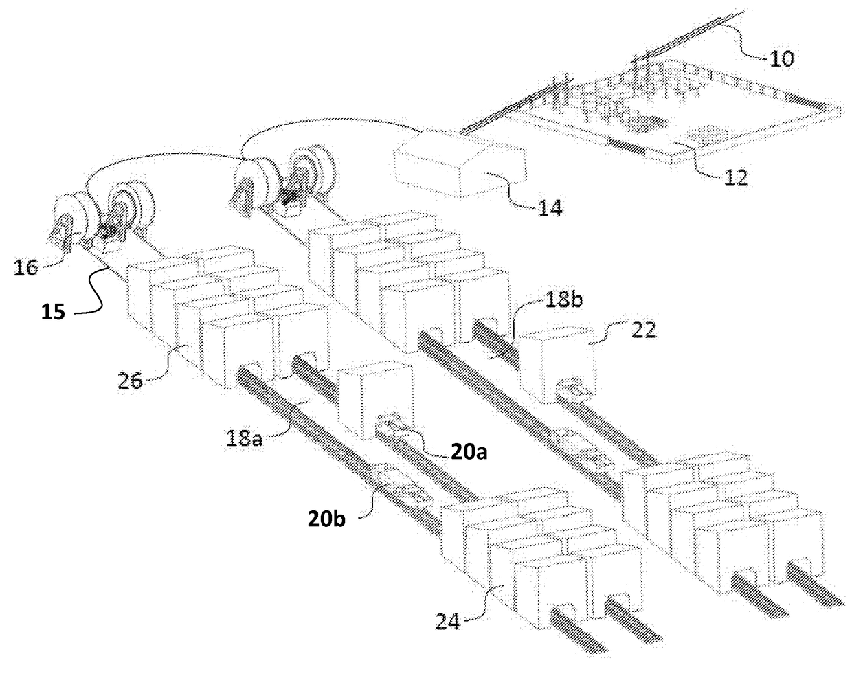
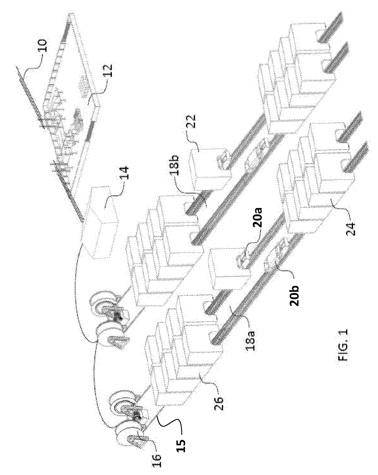
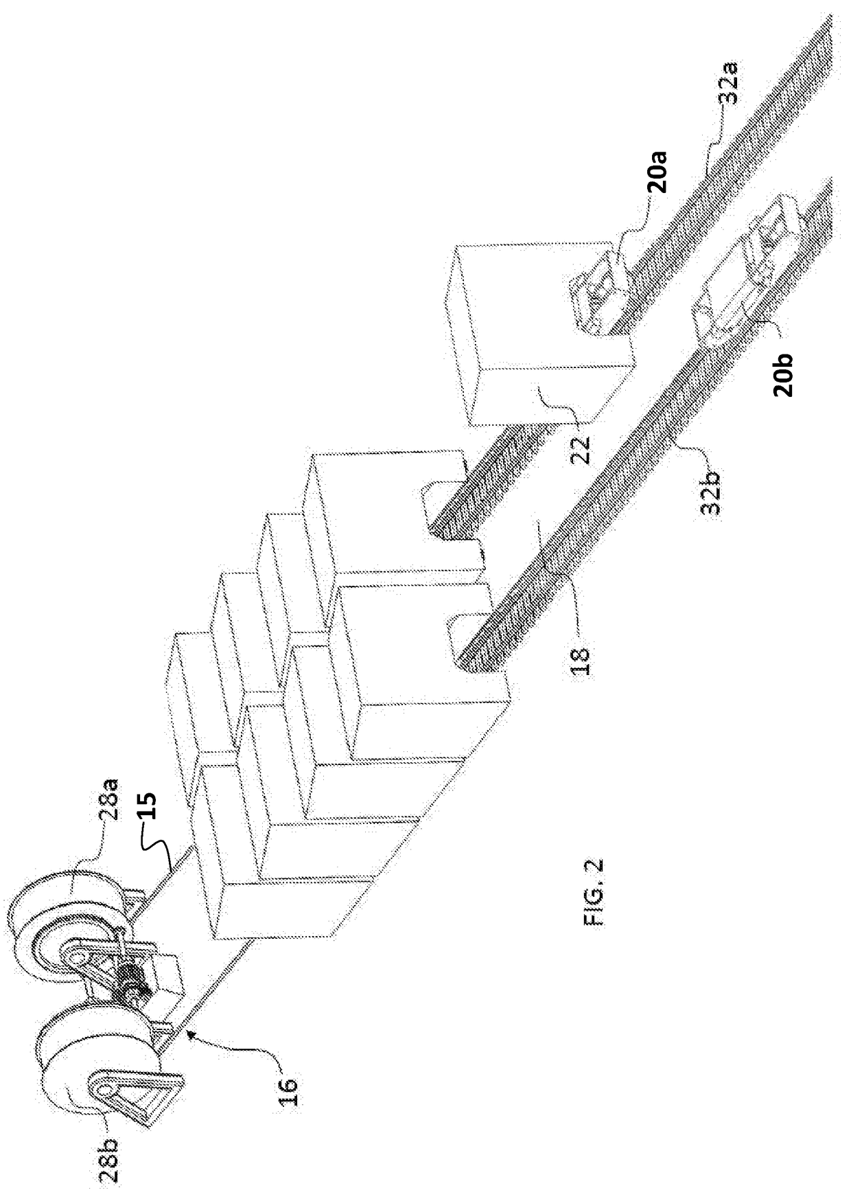
[0033]A exemplary embodiment of the ridgeline cable drive electric energy storage system is made up of a number of individual modules. In this manner, the system can effectively be varied in size from 10 to several hundred-megawatt power and the output can be finitely controlled to perform ancillary services. Referring to the drawings, a typical system layout is shown in FIG. 1. A transmission line 10 provides connection to a utility grid to receive excess power as input to the system storage or transmit power from the system on demand from the utility. An electric substation 12 connects the transmission line 10 to a power control system 14 and winch sets 16, which will be described in greater detail subsequently. The power control system 14 is responsive to the utility grid to store excess electrical power and to generate electrical power upon demand employing the system elements described herein. A number of funicular track sets carry consists 20a, 20b comprised of one or more shu...


PUM


Abstract

A highly efficient, utility scale energy storage system employs large masses transported uphill to store energy and downhill to release energy. An electric powered cable winch or chain drive shuttles the masses between two storage yards of different elevations separated by a steep incline on rail vehicles supported by track and operated by an automated control system.

Description

REFERENCE TO RELATED APPLICATIONS[0001]This application claims priority of U.S. provisional application Ser. No. 62 / 301,466 having a filing date of Feb. 29, 2016 entitled RIDGELINE CABLE DRIVE ELECTRIC ENERGY STORAGE SYSTEM having a common assignee as the present application, the disclosure of which is incorporated herein by reference.BACKGROUNDField[0002]The present invention relates generally to electric power storage and generation. More particularly, the present invention provides a system for gravitational potential energy storage employing electrically driven rail consists carrying off loadable masses between lower and upper storage yards. Potential energy is stored by employing electrical grid power for transport of the masses from the lower to upper storage facility using motor powered winch sets. Potential energy is recovered and returned to the electrical grid by generator operation of the winch set motors during transport of the masses from the upper to lower storage yard...

Claims


Application Information

Patent Timeline
Patent Type & Authority Applications(United States)
IPC IPC(8): H02J15/00B61C17/06H02K7/00
CPCH02J15/00B61C17/06H02K7/00B61D3/16H02J3/28B61B9/00B61D45/001Y02T10/7072Y02T30/00Y02E60/16F03G3/094F03G3/00B60L8/00B60L9/28
Inventor PEITZKE, WILLIAM R.BROWN, MATTHEW B.
Owner ADVANCED RAIL ENERGY STORAGE
Learn More