Cryogenic Liquid Tank

a cryogenic liquid tank and liquid tank technology, applied in water supply installation, container discharging methods, manufacturing tools, etc., can solve the problems of unfavorable high-altitude, long-duration aircraft, and hydrogen weighing about 10 to 20, and achieve the effect of changing the thermal conductivity of any given portion of the wall

Active Publication Date: 2010-07-29
AEROVIRONMENT INC
View PDF51 Cites 19 Cited by
  • Summary
  • Abstract
  • Description
  • Claims
  • Application Information

AI Technical Summary

Benefits of technology

[0013]An advantage of this configuration is that an aerogel insulator portion of the wall, which is a large and typically curved structure, can be constructed in manageable pieces and then assembled. Moreover, for a given tank design, the thermal conductivity of any given portion of the wall can be changed by changing only those pieces that cover that wall portion. Thus, each manufactured tank can be customized to a specific variation in thermal conductivity, based on the anticipated use of the tank, by only changing out the portions of the tank insulation that are different from a baseline design.
[0014]In a third aspect, around an inner-most layer that defines and substantially surrounds a fluid storage space, is a first set of one or more tubes extending from within the...

Problems solved by technology

However, practical considerations have largely prevented its use.
Typical tanks for storing compressed gaseous hydrogen have a weight of about 10 to 20 times that of the hydrogen stored, and are not likely practical for high-altitude, long-duration aircraft.
However, these tanks are not intended for ...

Method used


Image

  • Cryogenic Liquid Tank
  • Cryogenic Liquid Tank
  • Cryogenic Liquid Tank

Examples


Embodiment Construction

[0027]The invention summarized above and defined by the enumerated claims may be better understood by referring to the following detailed description, which should be read with the accompanying drawings. This detailed description of particular preferred embodiments of the invention, set out below to enable one to build and use particular implementations of the invention, is not intended to limit the enumerated claims, but rather, it is intended to provide particular examples of them.

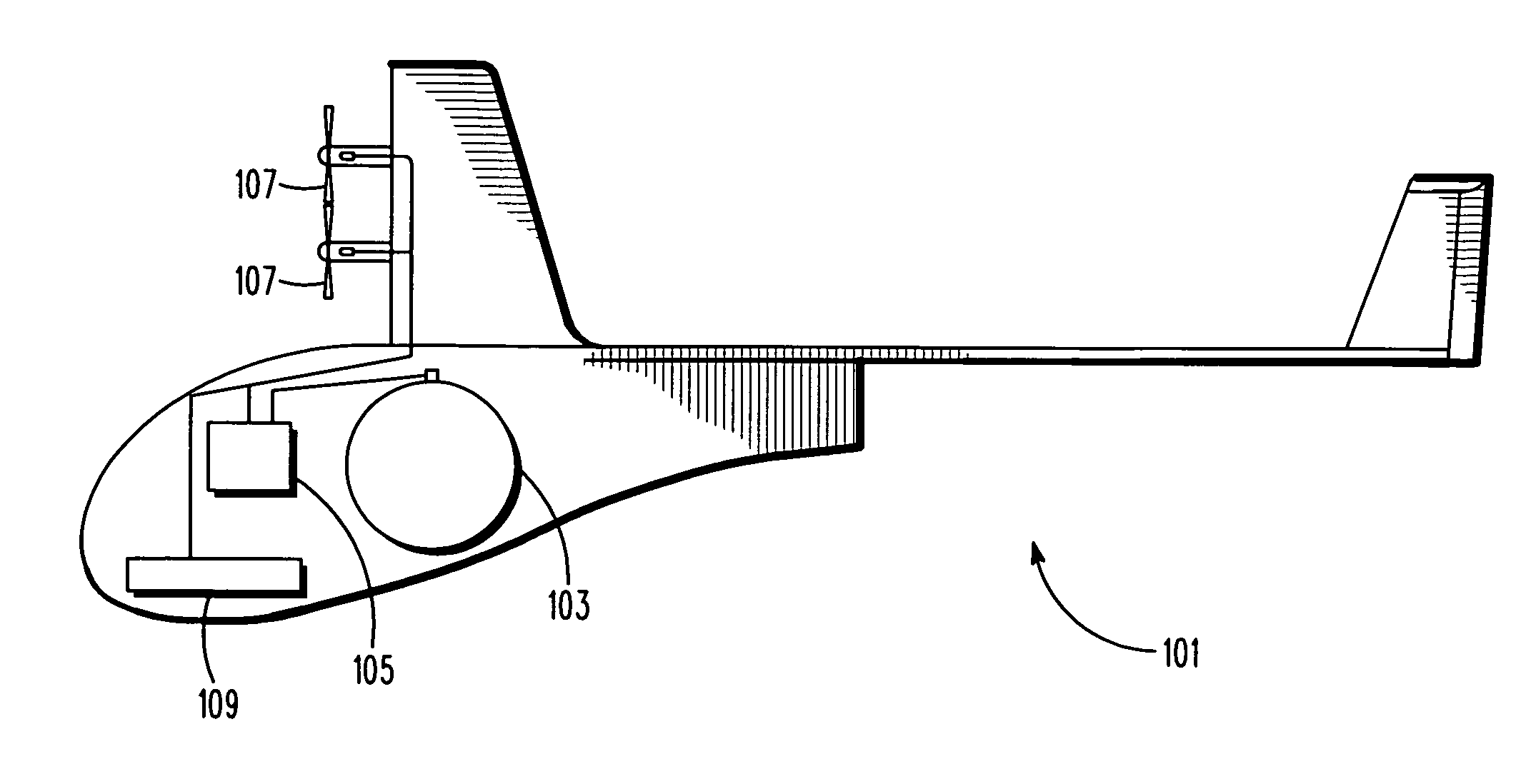
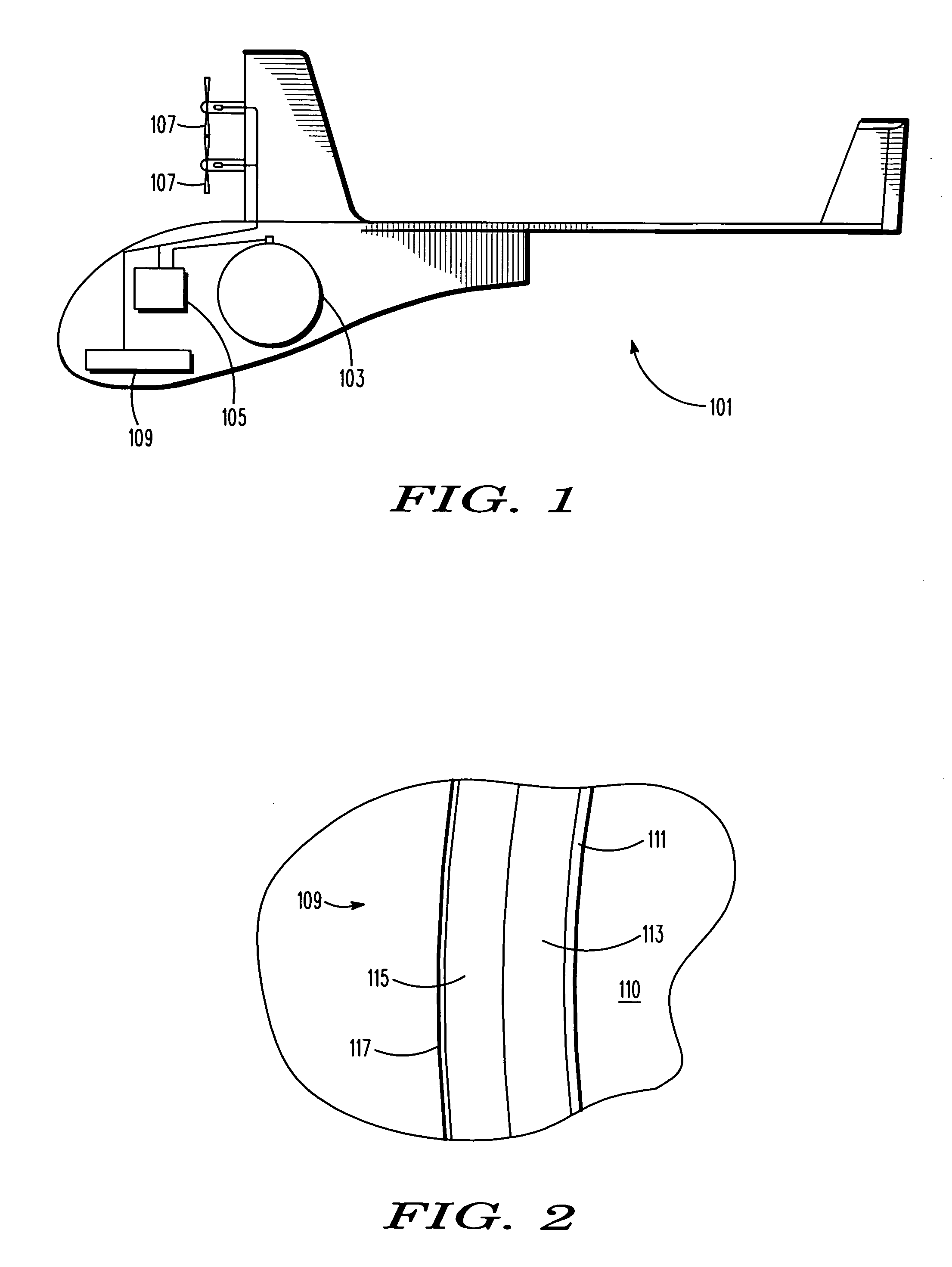
[0028]With reference to FIG. 1, typical embodiments of the present invention reside in a liquid hydrogen tank for a high-altitude long-endurance aircraft. The embodiment is well suited for use by an unmanned long-duration aircraft 101 that is configured to fly in the stratosphere. The aircraft includes one or more tanks 103 to carry hydrogen fuel. Hydrogen gas that boils off from the tank is piped to a power converter 105 (which is typically a fuel cell or internal combustion engine). The power converter...


PUM

PropertyMeasurementUnit
Pressureaaaaaaaaaa
Flow rateaaaaaaaaaa
Sizeaaaaaaaaaa

Abstract

A hydrogen storage tank for a hydrogen fueled aircraft. The tank has a wall made of layers of aerogel sections around a hard shell layer, sealed within a flexible outer layer, and having the air removed to form a vacuum. The periphery of each layer section abuts other sections of that layer, but only overlies the periphery of the sections of other layers at individual points. The wall is characterized by a thermal conductivity that is lower near its gravitational top than its gravitational bottom. The tank has two exit passageways, one being direct, and the other passing through a vapor shield that extends through the wall between two layers of aerogel. A control system controls the relative flow through the two passages to regulate the boil-off rate of the tank.

Description

[0001]This application claims the benefit of U.S. provisional Application No. 61 / 194,054, filed Sep. 23, 2008, which is incorporated herein by reference for all purposes.[0002]The present invention relates generally to a cryogenic fluid tank and, more particularly, to methods and apparatus that provide for lightweight containment of liquid hydrogen and are suitable for long-duration aircraft.BACKGROUND OF THE INVENTION[0003]Hydrogen is an attractive fuel for high-altitude, long-duration aircraft because it contains about 2.8 times the energy per pound as compared with traditional hydrocarbon fuels. In aircraft applications requiring very long-range or endurance, the high specific energy of hydrogen may be a key enabler. However, practical considerations have largely prevented its use. While the specific energy of hydrogen is very high, the energy per unit volume is comparatively low.[0004]In order to take advantage of the high specific energy of hydrogen, the associated tanks are pr...

Claims


Application Information

Patent Timeline
IPC IPC(8): F17C13/00B29C65/00B23P11/00
CPCF17C1/12Y10T29/49F17C2203/0325F17C2203/0329F17C2203/0358F17C2203/0391F17C2203/0395F17C2203/0604F17C2203/0629F17C2203/0643F17C2203/0646F17C2203/0673F17C2205/0314F17C2205/0332F17C2205/0352F17C2209/22F17C2209/221F17C2209/227F17C2209/238F17C2221/012F17C2223/0161F17C2223/033F17C2223/047F17C2227/0304F17C2227/0306F17C2227/0381F17C2250/0408F17C2250/043F17C2250/0636F17C2260/012F17C2260/033F17C2265/034F17C2270/0189Y02E60/321Y10T29/49826F17C2201/0128Y10T137/0318Y02E60/32F17C3/02F17C2250/03F17C2250/0404
Inventor BROOKS, ALEC NELSONHIBBS, BART DEANTHOMPSON, DAVID ROBERT
Owner AEROVIRONMENT INC
Why Eureka
Try Eureka