Surface Grinding Machine and Grinding Head Therefor

a surface grinding machine and grinding head technology, applied in the direction of grinding heads, gear teeth, gear teeth, etc., can solve the problems of excessive grinding disks, energy and manpower, and low spots of floor surfaces that cannot be effectively ground and polished

Inactive Publication Date: 2010-07-29
AMANO PIONEER ECLIPSE CORP
View PDF34 Cites 30 Cited by
  • Summary
  • Abstract
  • Description
  • Claims
  • Application Information

AI Technical Summary

Problems solved by technology

In the use of such machines, however, because of the uneven surfaces of floors and the planar surfaces of grinding disks, it has been found that low spots of floor surfaces are not effectively ground and polished unless an excessive amount of concrete or stone is removed to make the floor even and planar.
Such condition

Method used


Image

  • Surface Grinding Machine and Grinding Head Therefor
  • Surface Grinding Machine and Grinding Head Therefor
  • Surface Grinding Machine and Grinding Head Therefor

Examples


Embodiment Construction

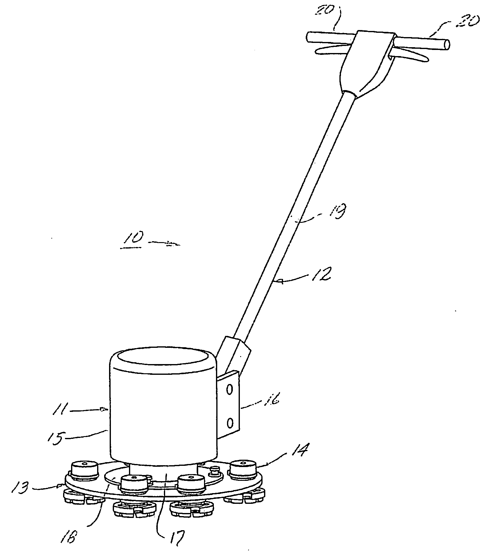
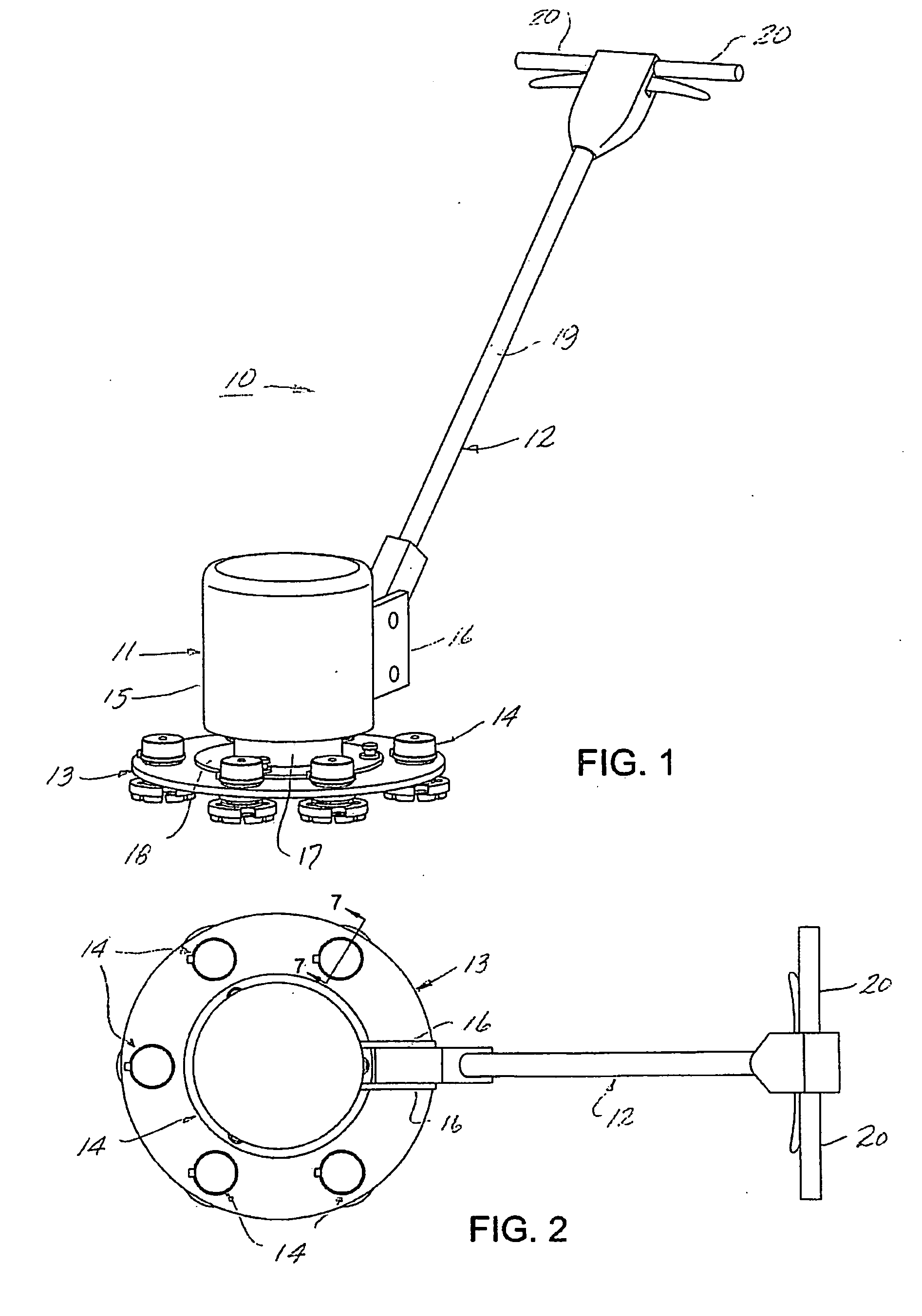
[0012]Referring to FIGS. 1 and 2 of the drawings, there is illustrated a floor grinding machine 10 embodying the present invention which generally includes a motor assembly 11, a handle assembly 12, a planetary disk 13 and a plurality of grinding head units 14. Motor assembly 11 includes a motor mounted within a housing 15 provided with a set of brackets 16, 16, having a depending output shaft. Mounted on the end of the output shaft is a carrier member 17 provided with an annular flange 18. Handle assembly 12 includes an elongated member 19 having a lower end received within and pivotally connected to brackets 16, 16, and a pair of handles 20, 20 disposed at an upper, free end thereof which may be gripped by an operator to guide the machine over a floor surface to be worked. The motor of the machine may be either an internal combustion engine or an electric motor and may be operated in the conventional manner with controls mounted on the handle assembly adjacent handles 20, 20.

[0013...


PUM


Abstract

A surface grinding machine generally consisting of a drive means provided with an output shaft; a planetary disk mounted on the shaft; and at least two grinding head units mounted on the planetary disk, each including a housing mounted on the planetary disk, a shaft having a flange portion, journaled in the unit housing, resilient means interposed between the housing and the flange portion of the unit shaft and a disk provided with a grit surface disposed on an outer side of the flange, portion of the unit shaft.

Description

FIELD OF THE INVENTION[0001]This invention relates to a machine for grinding surfaces such as concrete floors and the like, and more particularly to such a machine which is more effective in grinding rough surfaces into smooth surfaces.BACKGROUND OF THE INVENTION[0002]In the finishing of concrete and stone floors, it customarily is the practice to grind and polish the surfaces of such floors to provide consistently smooth finishes. Such finishing typically is performed by machines consisting of a motor, a planetary disk mounted on an output shaft of the motor and a disk provided with a grit surface mounted on the planetary disk. In the use of such machines, however, because of the uneven surfaces of floors and the planar surfaces of grinding disks, it has been found that low spots of floor surfaces are not effectively ground and polished unless an excessive amount of concrete or stone is removed to make the floor even and planar. Such condition results in not only the removal excess...

Claims


Application Information

Patent Timeline
IPC IPC(8): B24B7/18B24B23/02B24D7/18
CPCB24B41/047B24B7/186
Inventor HAMM, DERRICK L.SMITH, JOHN E.WARD, WILLIS D.
Owner AMANO PIONEER ECLIPSE CORP
Why Eureka
Try Eureka