Battery state monitoring circuit and battery device
a battery state monitoring and circuit technology, applied in the direction of battery overcharge protection, safety/protection circuits, transportation and packaging, etc., can solve the problems of significant worse usability and the discharge of respective batteries
- Summary
- Abstract
- Description
- Claims
- Application Information
AI Technical Summary
Benefits of technology
Problems solved by technology
Method used
Image
Examples
Embodiment Construction
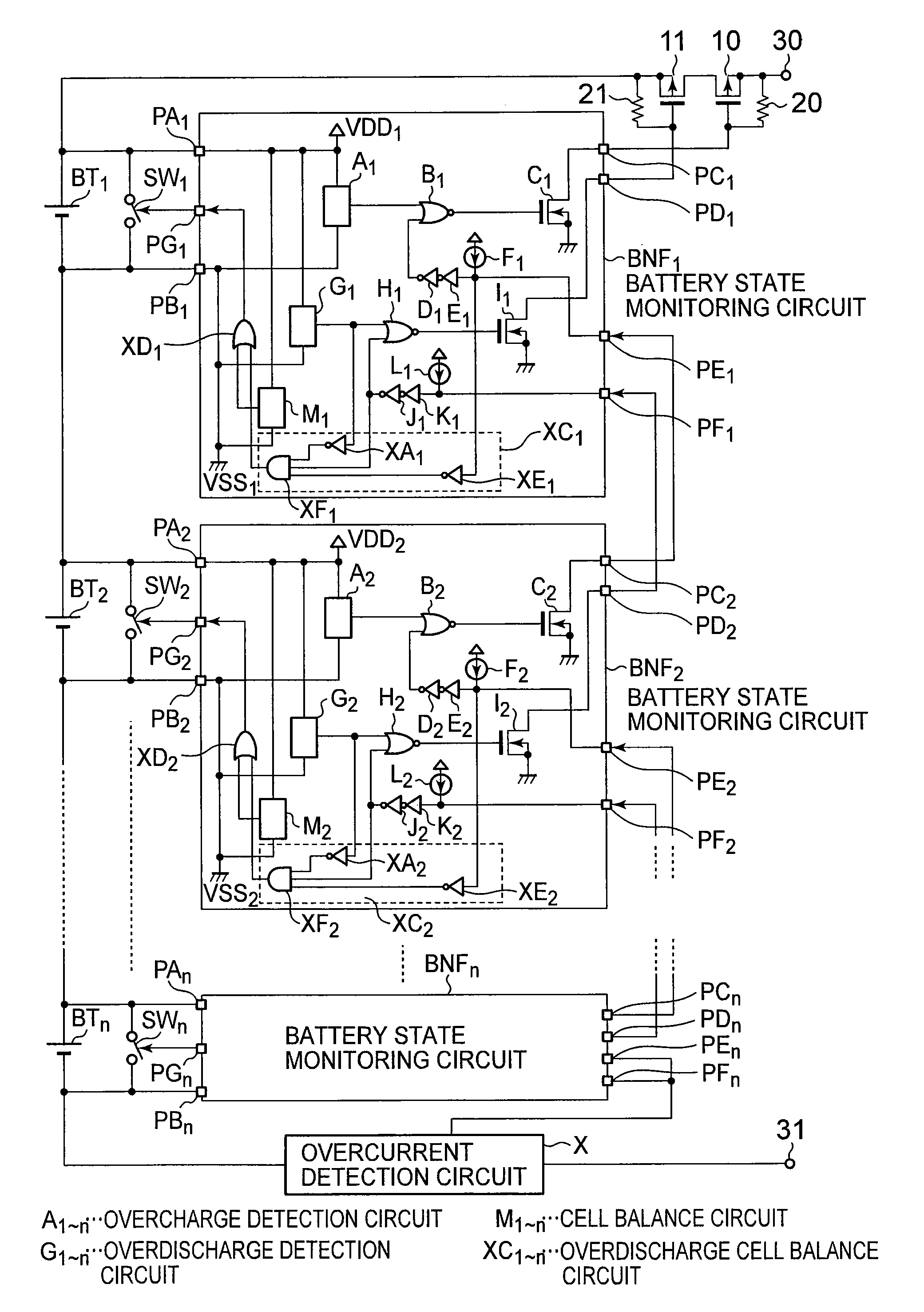
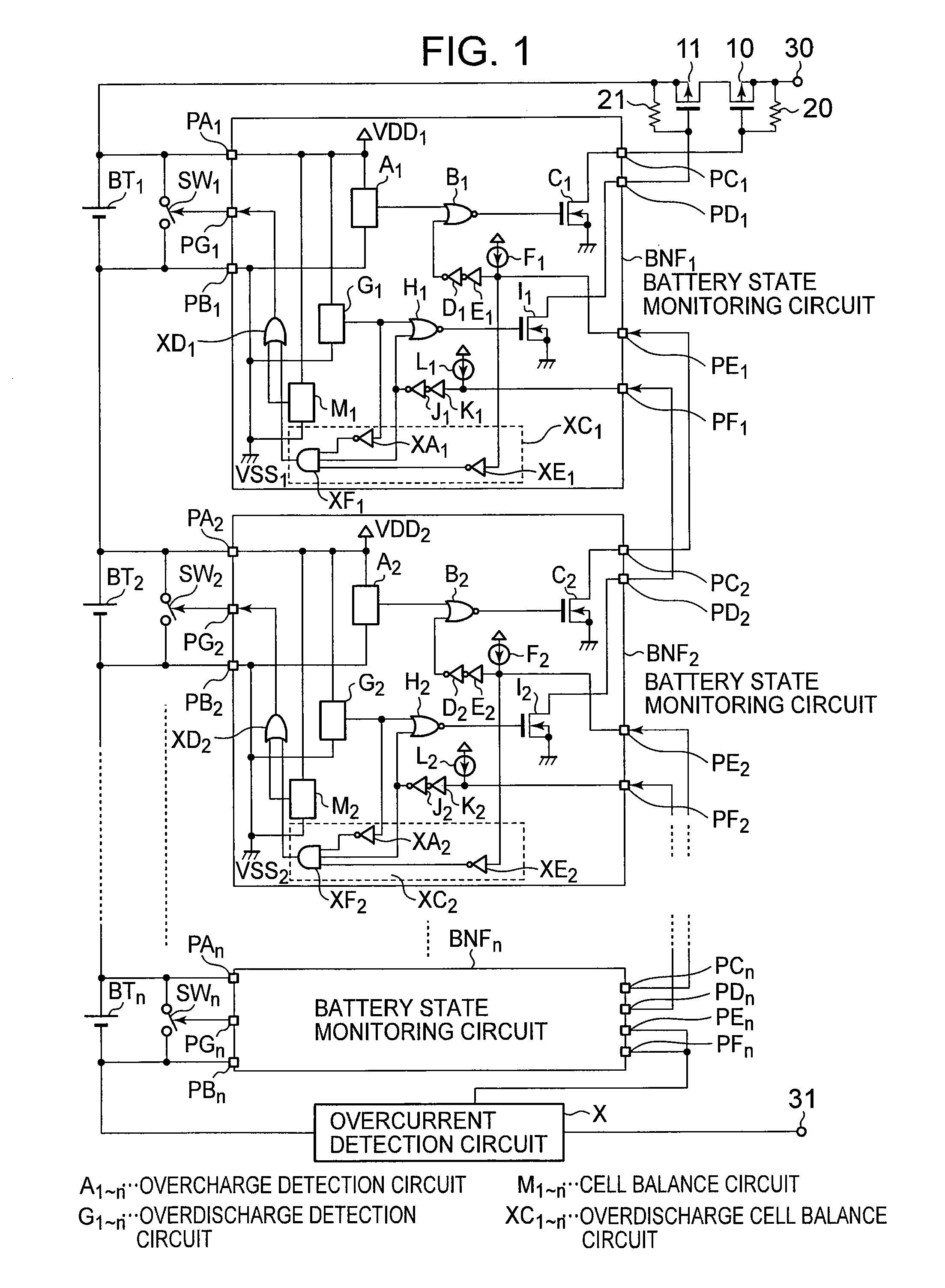
[0037]FIG. 1 illustrates a circuit diagram of a battery device according to an embodiment of the present invention.
[0038]The battery device according to the embodiment of the present invention includes n batteries BT1 to BTn that are connected in series, n switches (cell balance switch circuits) SW1 to SWn that are respectively connected in parallel with the batteries BT1 to BTn, n battery state monitoring circuits BNF1 to BNFn that are individually provided in correspondence with the batteries BT1 to BTn, a first transistor (charging P-channel transistor) 10, a second transistor (discharging P-channel transistor) 11, a first resistive element (first bias resistive element) 20, a second resistive element (second bias resistive element) 21, an overcurrent detection circuit X, a first external terminal 30, and a second external terminal 31.
[0039]The battery state monitoring circuit BNF1 includes an overcharge detection circuit A1, a first NOR circuit B1, a first output transistor C1, ...
PUM
 Abstract
Description
Claims
Application Information
 - R&D
- Intellectual Property
- Life Sciences
- Materials
- Tech Scout
- Unparalleled Data Quality
- Higher Quality Content
- 60% Fewer Hallucinations
Browse by: Latest US Patents, China's latest patents, Technical Efficacy Thesaurus, Application Domain, Technology Topic, Popular Technical Reports.
© 2025 PatSnap. All rights reserved.Legal|Privacy policy|Modern Slavery Act Transparency Statement|Sitemap|About US| Contact US: help@patsnap.com


