Method and Apparatus for Turning a Log for Processing in a Sawmill

a technology of a sawmill and a log is applied in the field of method and apparatus for turning a log for processing in a sawmill, which can solve the problems of increasing the energy consumption of the apparatus, and increasing the complexity of the apparatus

Inactive Publication Date: 2010-08-19
CORDELL HENRY L
View PDF12 Cites 8 Cited by
  • Summary
  • Abstract
  • Description
  • Claims
  • Application Information

AI Technical Summary

Benefits of technology

[0014]FIG. 4 is a view like FIGS. 2 and 3 showing the apparatus with the pusher arms engaging the log to assist in turning of the log onto its first cut flat surface to engage the carriage; and

Problems solved by technology

The log turner of this reference travels with the sawmill carriage, which adds to the complexity of the apparatus and increases its energy consumption relative to a log turner that is capable of performing its intended function at a fixed location.
This apparatus is quite complex, requiring as it does a rotational drive motor that operates a speed reducer through a pulley and belt drive.
This apparatus is capable of orienting the log to change the orientation of its longitudinal central axis, as is shown in FIGS. 6A-6D, and this is a degree of complexity, and expense, that is not required in a typical sawmill operation.

Method used


Image

  • Method and Apparatus for Turning a Log for Processing in a Sawmill
  • Method and Apparatus for Turning a Log for Processing in a Sawmill
  • Method and Apparatus for Turning a Log for Processing in a Sawmill

Examples


Embodiment Construction

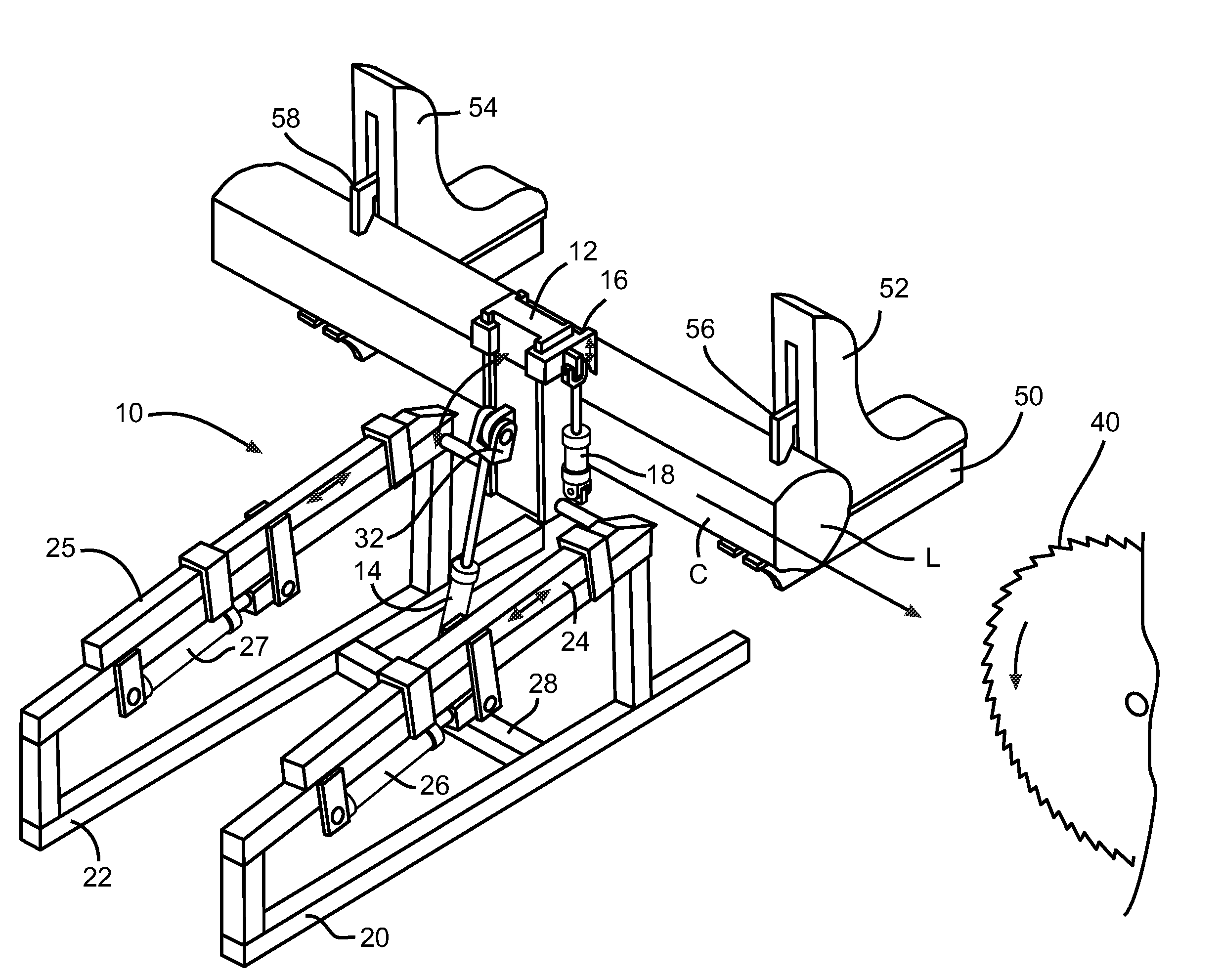
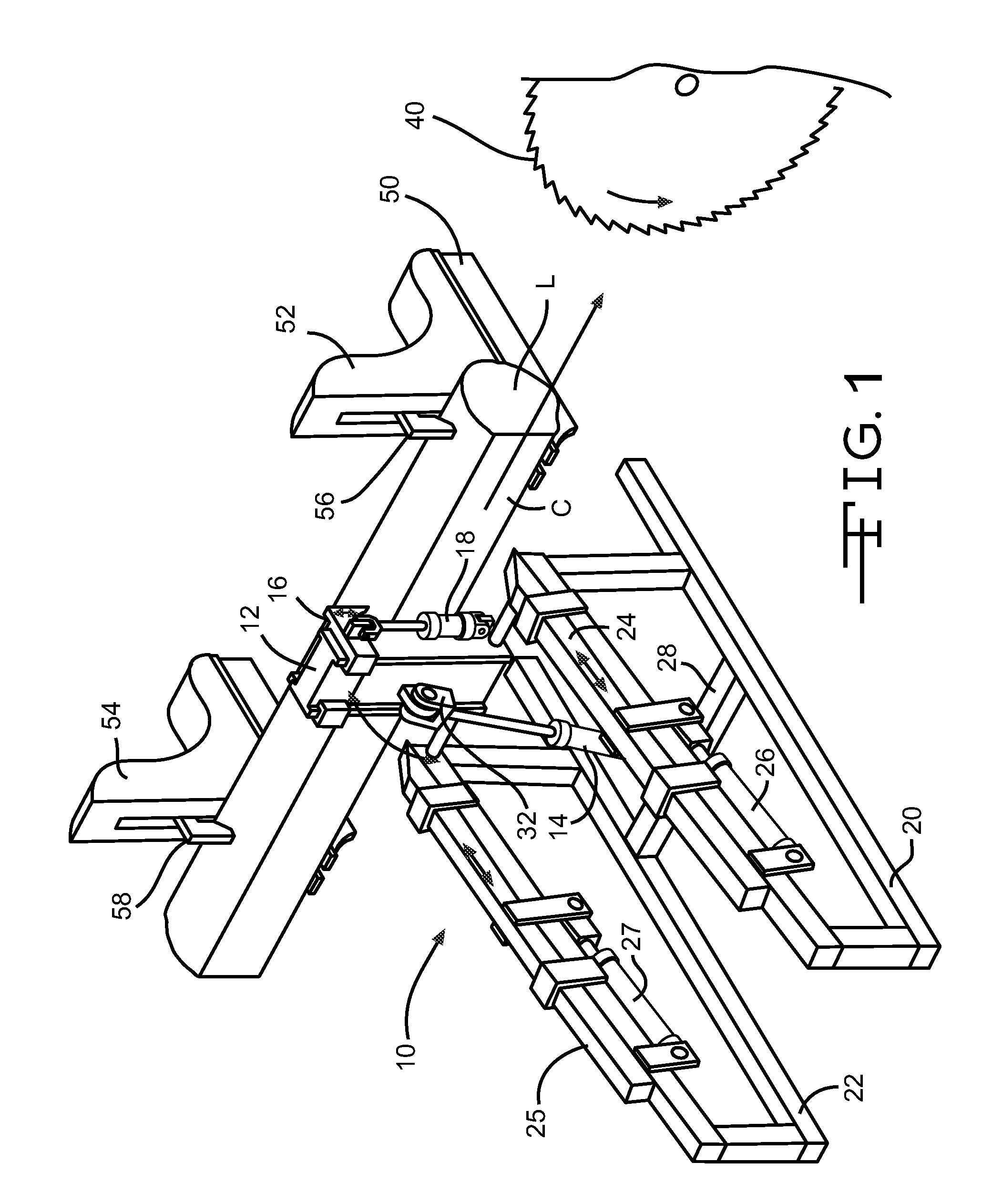
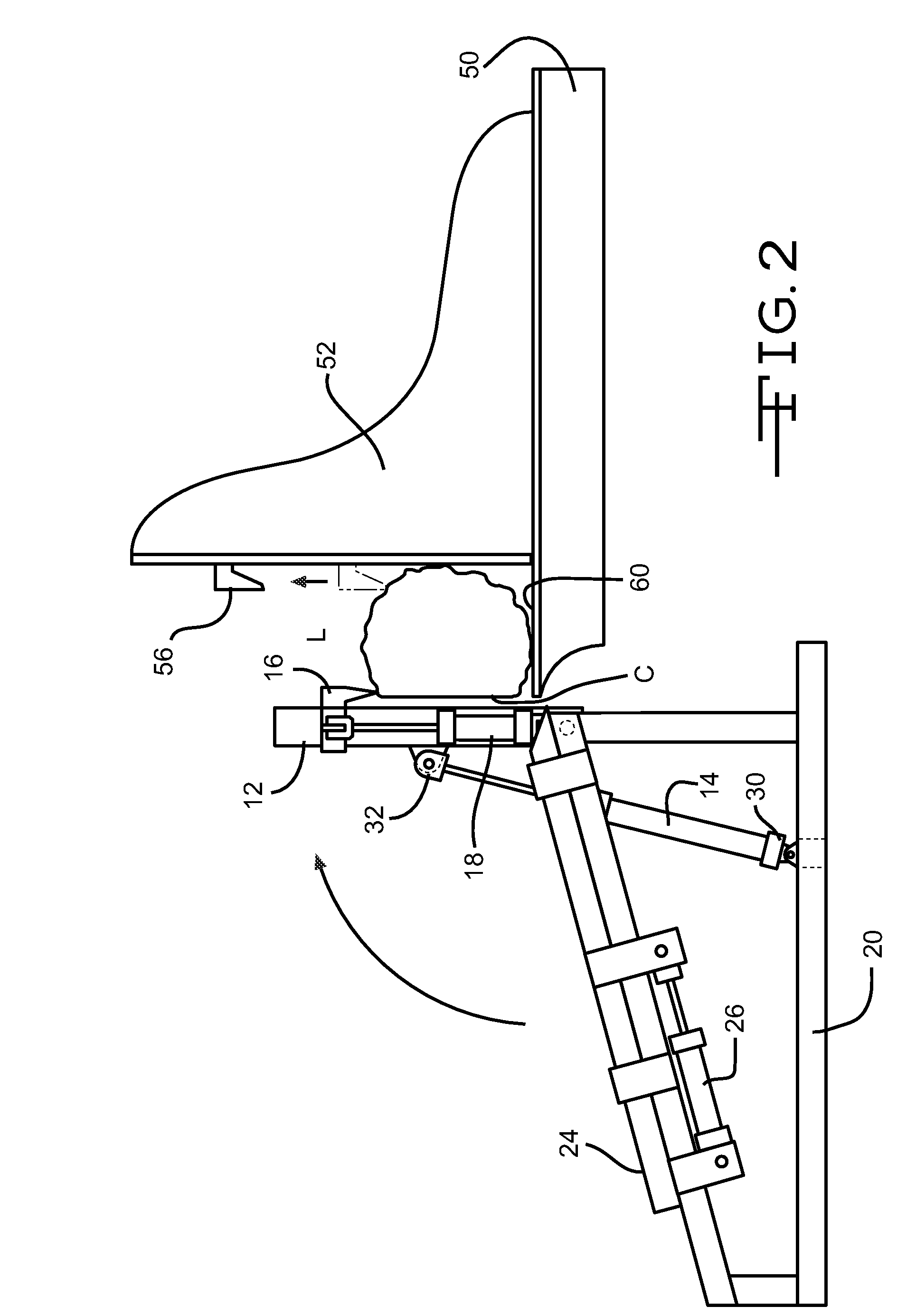
[0016]With reference to FIGS. 1-5, a log turner apparatus according to a preferred embodiment of the present invention is indicated generally by reference numeral 10 in the drawings. The log turner apparatus 10 is used to turn a log L to be carried to a saw 40 by a reciprocating carriage 50, which is conventional in the prior art. The reciprocating carriage 50 has a spaced-apart pair of movable headblocks 52, 54 that reciprocate with the reciprocating carriage 50 as well as are hydraulically movable lateral to the reciprocating carriage 50. The movable headblocks 52, 54 have vertically reciprocating dogs 56, 58, respectively, that secure the log L on the reciprocating carriage 50 as the reciprocating carriage 50 advances toward and away from the saw 40.

[0017]The log turner apparatus 10, which does not reciprocate with the reciprocating carriage 50, is located along side the reciprocating carriage 50 and has a tilting arm 12, mounted between upright stands 20, 22 pivotally oscillatin...


PUM


Abstract

A log on a surface of a translatable carriage against head blocks of the carriage is turned by rolling the log on the surface of the translatable carriage after releasing the log from engagement by reciprocating dogs that are carried by the head blocks and before advancing the translatable carriage toward a saw. The turning of the log on the surface is accomplished by engaging the log by a reciprocating dog that is carried by a pivoting arm at a location away from the engagement of the log by the reciprocating dogs that are carried by the head blocks. After turning of the log on the surface of the translatable carriage, the log is pushed along the surface of the translatable carriage back toward the head blocks by pushing against the log by spaced-apart double-acting cylinders that are mounted on non-translatable stands respectively.

Description

CROSS-REFERENCES TO RELATED APPLICATIONS[0001]Not applicable.FEDERALLY SPONSORED RESEARCH OR DEVELOPMENT[0002]Not applicable.REFERENCE TO SEQUENCE LISTING[0003]Not applicable.BACKGROUND OF THE INVENTION[0004]1. Field of the Invention[0005]This invention relates in general to an apparatus and a method for turning a log about its longitudinal central axis at a fixed location in preparation for advancing the log on a reciprocating carriage to have a portion of the log removed by a saw in a sawmill. More specifically, the invention is used to turn a log 90 degrees “face down” after each return of the carriage carrying the log in a sawmill operation.[0006]2. Description of Related Art[0007]U.S. Pat. No. 5,950,517 (Yoder) discloses a log turner for turning a log about its longitudinal central axis. The log turner of this reference travels with the sawmill carriage, which adds to the complexity of the apparatus and increases its energy consumption relative to a log turner that is capable o...

Claims


Application Information

Patent Timeline
Patent Type & Authority Applications(United States)
IPC IPC(8): B27B1/00B27B31/00
CPCB27B31/04B27B29/08
Inventor CORDELL, HENRY L.
Owner CORDELL HENRY L
Why Eureka
Try Eureka