
Remote input device

a remote input and input technology, applied in the field of input devices, can solve the problems of difficult use, high cost of complex remote controls, and discourage casual users from operating equipmen

Active Publication Date: 2010-08-26
SONY COMPUTER ENTERTAINMENT INC
View PDF31 Cites 135 Cited by
  • Summary
  • Abstract
  • Description
  • Claims
  • Application Information

AI Technical Summary

Benefits of technology

[0011]An embodiment of the invention is an input device that provides users with a pointing capability. This embodiment includes a sender portion and a receiver portion. The sender portion is adapted to be manipulated by a user to specify a target point within a target area. The sender portion projects a light beam including a pattern on to the target area. A receiver portion includes one or more sensor units located in or near the target...

Problems solved by technology

Many consumer electronics devices, such as televisions, video playback and recording devices, and cable boxes, have numerous complicated and esoteric functions that need to be controlled by a user from a distance.
However, complicated remote controls are expensive and discourage casual users from operating the equipment.
However, because menu-based interfaces often bury functions under one or more menus or sub-menus, they are often difficult to use.
However, in many applications, the user does not have access to a flat surface.
In these applications, a mouse is difficult and inconvenient to use.
As a result of this disruption, mice are not widely used in casual environments where the user is not likely to be seated in front of a flat surface.
Unfortunately, users often find controlling a pointer using a joystick to be difficult, non-intuitive, and frustrating.
As a result, these types of devices cannot operate from non-raster scanned displays, such as LCD, plasma, and non-CRT based projection displays.
This type of light gun is complicated and expensive, requiring the installation of a camera on the opposite wall from the target display.
The disadvantages of this device are its complexity, cost, size, and power consumption.
Moreover, this type of device is often only sensitive to large amounts of motion.

Method used


Image

  • Remote input device
  • Remote input device
  • Remote input device

Examples


Embodiment Construction

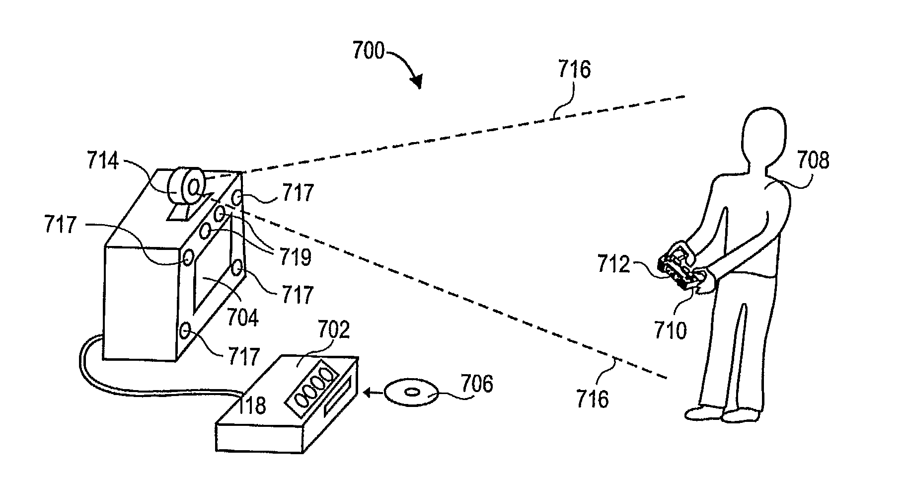
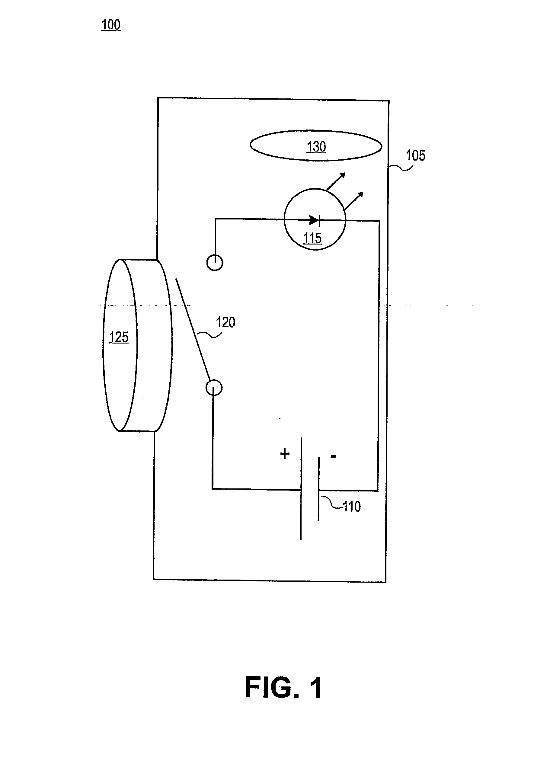
[0032]FIG. 1 illustrates a sender portion 100 of an embodiment of the invention. The sender portion 100 is adapted to be manipulated by a user. The user points the sender portion 100 at a target area to specify a target point. The position of the target point manipulates a pointer or other user interface element. In an embodiment, the target point is within the boundaries of a target area. An example target area is the screen of a display device, such as a television. In further embodiments, discussed below, the sender portion 100 allows the user to specify an absolute location for a pointer or user interface element and / or a relative movement of a pointer or user interface element from a previous location.

[0033]Sender portion 100 includes a housing 105, a battery or other power supply 110, and a light source 115. Light source 115 can emit visible or non-visible light, for example infrared light. Light source 115 can include a light bulb, light emitting diode (LED), or other type of...


PUM


Abstract

An input device providing users with a pointing capability includes a sender portion (100) and a receiver portion (200). The sender portion (100) is adapted to be manipulated by a user (the user manipulating button 125) to specify a target point within a target area. The sender portion projects a light beam (light output from light source 115) including a pattern onto the target area. A receiver portion (200) includes one or more sensor units (205, 210, 215) located in or near the target area. At least some of the sensor units (205, 210, 215) receive a portion of the light beam (light output from light source 115) regardless of the location of the target point within the target area. A processing unit (220) in the receiver portion (200) analyzes the portions of the light beam received by one or more sensor units (205, 210, 215) to determine an attribute of the target point. The attribute can be the location or relative motion of the target point. The receiver portion (200) may be integrated with a display device.

Description

CROSS-REFERENCE TO RELATED APPLICATIONS[0001]This application is a continuation in part of and claims the benefit of prior application Ser. No. 11 / 139,254 to Gregory A. Corson, entitled “REMOTE INPUT DEVICE”, filed May 27, 2005.FIELD OF THE INVENTION[0002]Embodiments of the invention are related to the field of input devices suitable for operating display devices and other electronic devices.BACKGROUND OF THE INVENTION[0003]Many consumer electronics devices, such as televisions, video playback and recording devices, and cable boxes, have numerous complicated and esoteric functions that need to be controlled by a user from a distance. Some manufacturers provide users with complicated remote controls that include dedicated buttons for all of the device's functions. However, complicated remote controls are expensive and discourage casual users from operating the equipment.[0004]As an alternative, the user interfaces for many consumer electronic devices employ on-screen displays to enab...

Claims


Application Information

Patent Timeline
IPC IPC(8): G09G5/08
CPCG06F3/0346G06F3/0325
Inventor CORSON, GREGORY A.ZALEWSKI, GARY MICHAEL
Owner SONY COMPUTER ENTERTAINMENT INC
Features
  • Generate Ideas
  • Intellectual Property
  • Life Sciences
  • Materials
  • Tech Scout
  • Unparalleled Data Quality
  • Higher Quality Content
  • 60% Fewer Hallucinations
Learn More