
Head mount display

Active Publication Date: 2010-09-09
BROTHER KOGYO KK
View PDF4 Cites 32 Cited by
  • Summary
  • Abstract
  • Description
  • Claims
  • Application Information

AI Technical Summary

Benefits of technology

[0015]The present invention is made under such circumstances, and it is an object of the present invention to provide a head mount display (hereinafter referred to as “HMD”) which can perform a display control which enhances visibility of ambient scenery including an operation object by reducing visibility of a region which disturbs an operation out of a reference image displayed by a display unit.
[0016]According to one aspect of the present invention, there is provided an HMD which includes a display unit, an imaging unit, a hand detection unit, a display control unit, and a determination unit. The display unit allows an image light corresponding to image information to be incident on an eye of an user together with an ambient light thus displaying an image corresponding to the image information in an overlapping manner with ambient scenery. The imaging unit images a range which includes at least a display region provided by the display unit out of a field of view of the user. The hand detection unit detects hands of the user by analyzing the image imaged by the imaging unit. The display control unit performs a control in which a reference image which is used as a reference when the user performs a predetermined operation is displayed by the display unit. The determination unit determines a region which is defined between one hand and the other hand of the user detected by the hand detection unit. The display control unit reduces visibility of the region which is determined by the determination unit out of the reference image displayed by the display unit for the user.

Problems solved by technology

However, the user uses his hands often during the operation and hence, the erasing of the reference image (virtual image) by the gesture of his hands or fingers may inevitably bring troubles such as the interruption of the operation into the operation.
Further, the virtual image display device requires a specific unit which specifies the image so that there exists a possibility that the virtual image display device becomes complicated.

Method used


Image

  • Head mount display
  • Head mount display
  • Head mount display

Examples


Embodiment Construction

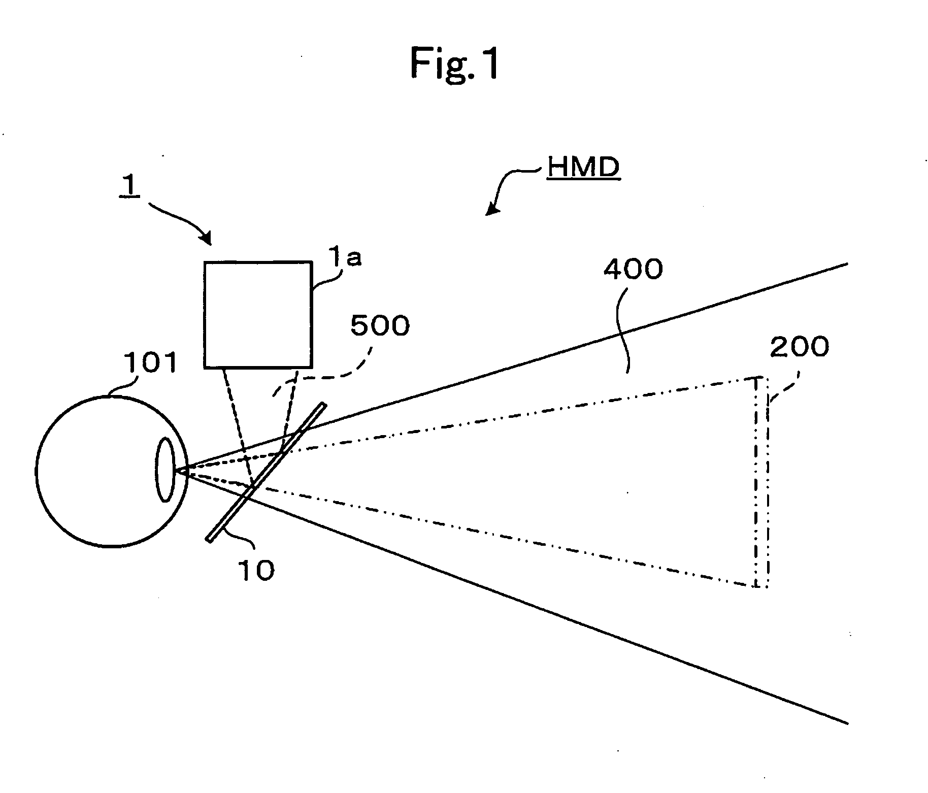
[0030]Hereinafter, one example of an HMD according to one embodiment is explained in conjunction with drawings. The explanation is made hereinafter assuming that an HMD is a retinal-scanning-type HMD in which an image light formed based on an image signal is scanned two-dimensionally, the scanned image light is projected onto an eye of a user thus forming an image on a retina. However, the HMD is not limited to the retinal-scanning-type HMD and the present invention is applicable to any HMD which includes a display unit which allows an image light corresponding to image information to be incident on an eye of a user together with an ambient light, and displays an image corresponding to the image information to the eye of the user in an overlapping manner with ambient scenery.

1. Summary of HMD

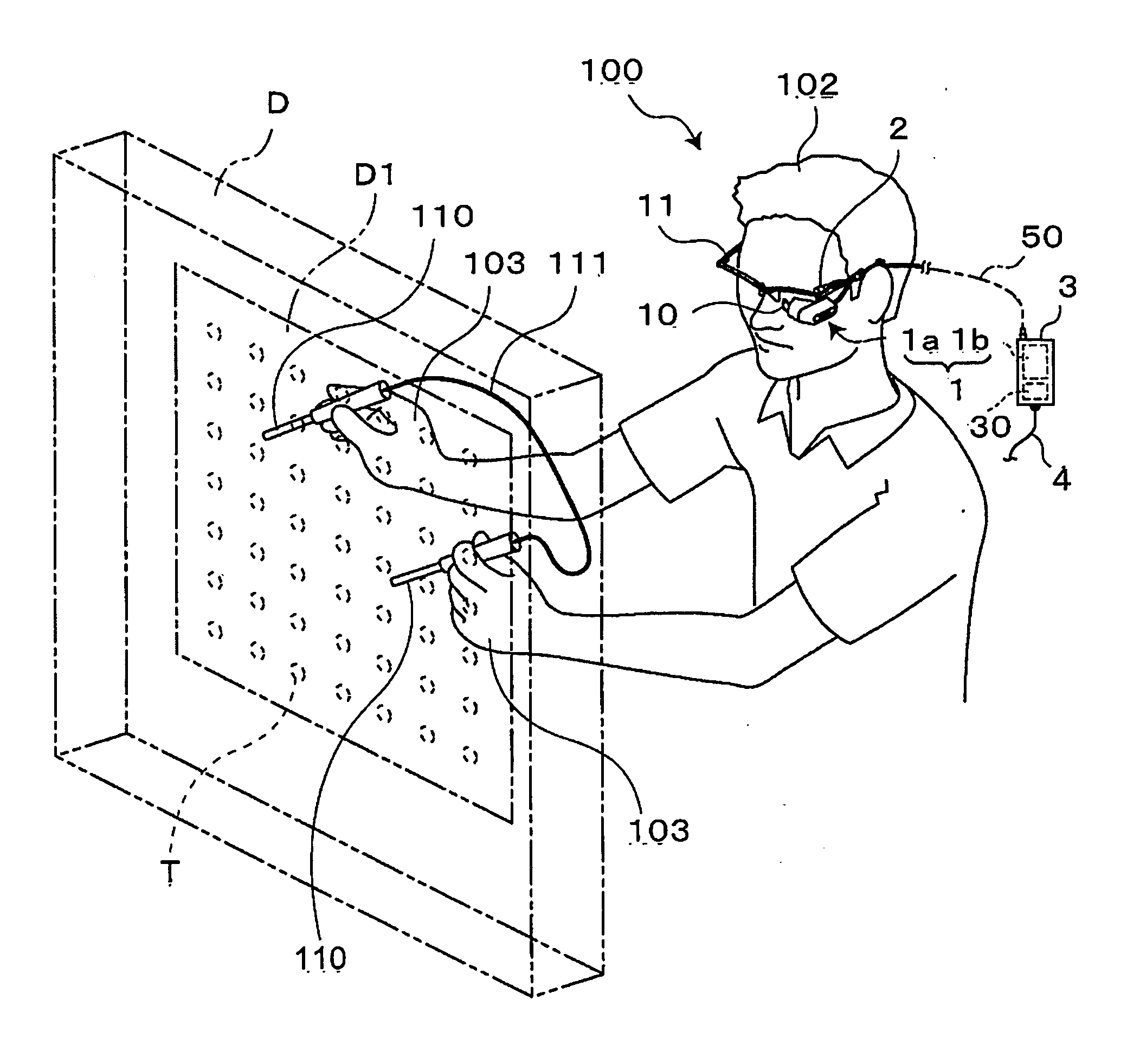
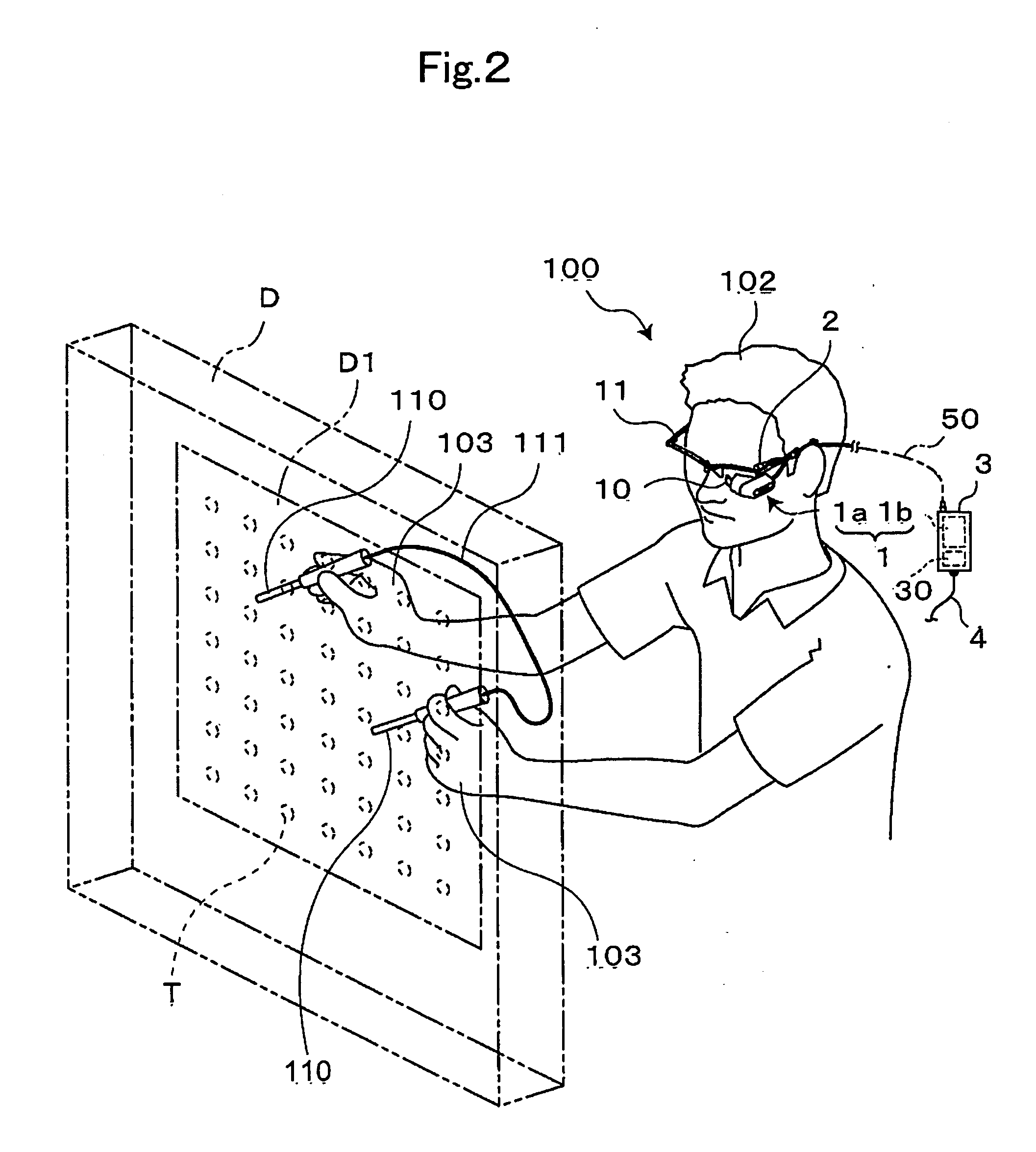
[0031]As shown in FIG. 1, the HMD according to this embodiment is configured to display, as a display image which constitutes a content, a reference image 200 such as an operation manual, for ex...


PUM


Abstract

In a head mount display, an imaging unit detects hands of a user in such a manner by imaging a range which includes at least a display region displayed by a display unit out of a field of view of a user. In displaying a reference image which is used as a reference when a user performs a predetermined operation, the head mount display reduces visibility of the reference image for the user in a region defined between one hand and the other hand of the user.

Description

CROSS-REFERENCE TO RELATED APPLICATIONS[0001]This application is based on and claims the benefit of priority from Japanese Patent Application No. 2009-055575 filed on Mar. 9, 2009, the entire contents of which are incorporated herein by reference.BACKGROUND[0002]1. Field[0003]The present invention relates to a head mount display.[0004]2. Description of the Related Art[0005]Conventionally, as one example of an image display device, there has been known a head mount display having a display unit which allows an image light corresponding to image information to be incident on an eye of a user together with an ambient light thus displaying an image corresponding to the image information in an overlapping manner with ambient scenery.[0006]As a mode where the head mount display is used, considered is a case where, in a state where a user wears the head mount display on his head, the user is engaged with a predetermined operation while displaying a reference image such as an operation manu...

Claims


Application Information

Patent Timeline
IPC IPC(8): G09G5/00G06F3/033G06F3/0346G06F3/038G06F3/048
CPCG02B27/017G06F3/011G02B2027/0187
Inventor SATO, TOMOHIRO
Owner BROTHER KOGYO KK
Learn More