
Image scanning apparatus and image scanning method

a scanning apparatus and scanning method technology, applied in the direction of electrical apparatus, instruments, computing, etc., can solve the problems of deterioration of reading efficiency, difficult maintenance and high cost, and the tendency of glossy originals to halve more, and achieve the effect of low cos

Inactive Publication Date: 2010-09-16
RICOH KK
View PDF21 Cites 8 Cited by
  • Summary
  • Abstract
  • Description
  • Claims
  • Application Information

AI Technical Summary

Benefits of technology

[0012]Accordingly, an object of the present invention is to provide an image scanning apparatus capable of forming high-quality scanned images at low cost, preventing halation images having dotted blanks when using a light source in which dotted light-emitting elements are linearly arrayed.

Problems solved by technology

However, these light sources largely vary in light quantity as time passes and have short lives, and are difficult to maintain and expensive.
In addition, glossy originals tends to occur halation more.
However, because a part the scanning light is totally reflected on the transparent material or shaded with a shade member to prevent halation, the light quantity of the scanning light lowers, resulting in deterioration of reading efficiency, or the extra shade member increases the cost.

Method used


Image

  • Image scanning apparatus and image scanning method
  • Image scanning apparatus and image scanning method
  • Image scanning apparatus and image scanning method

Examples


example 1

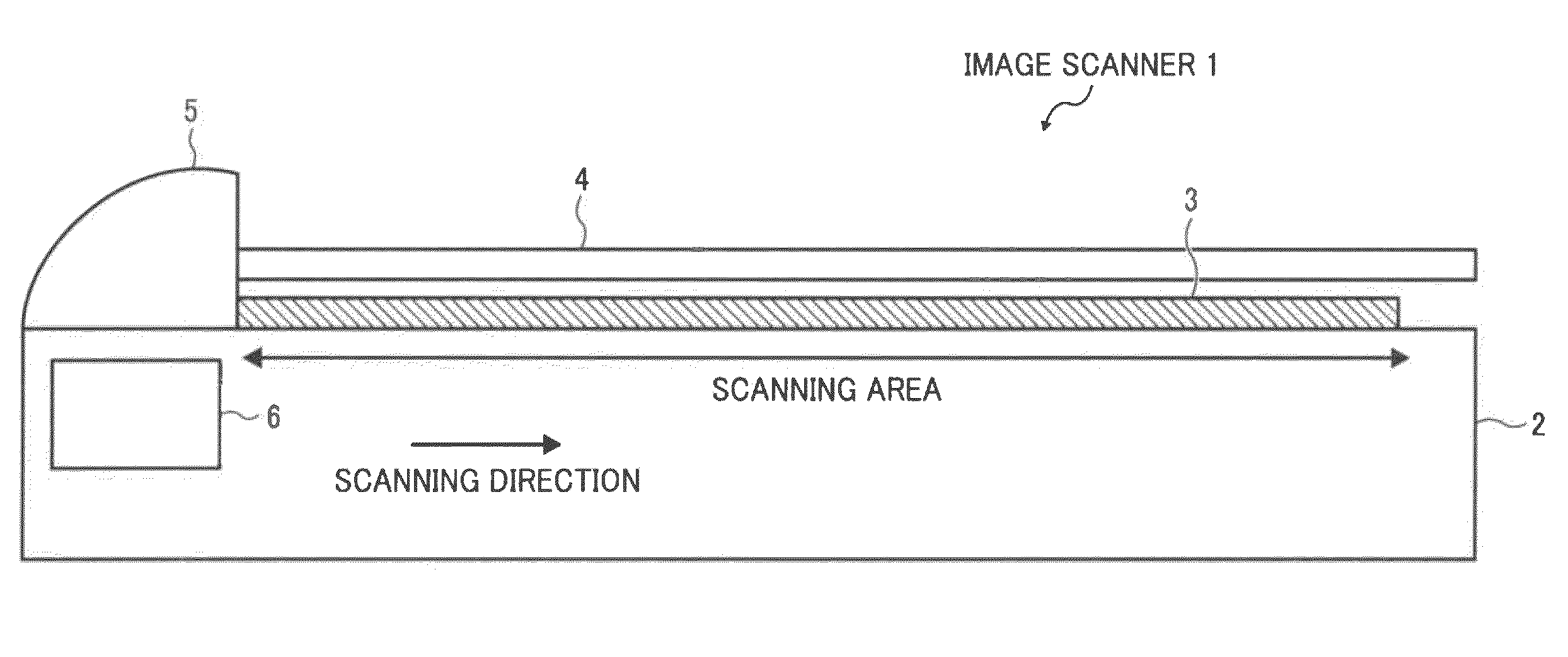
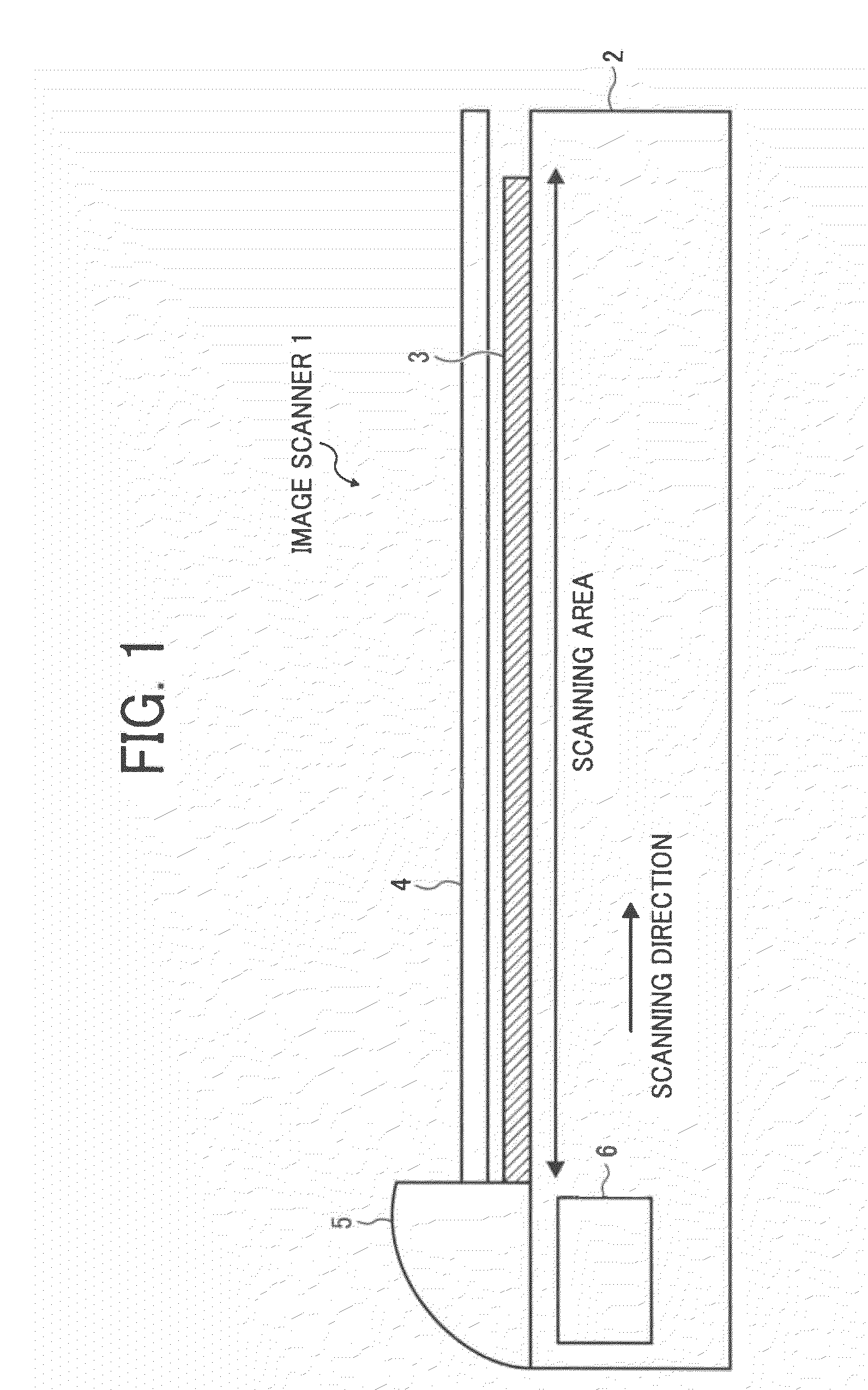
[0041]FIG. 1 is a schematic view illustrating an embodiment of the image scanning apparatus of the present invention.

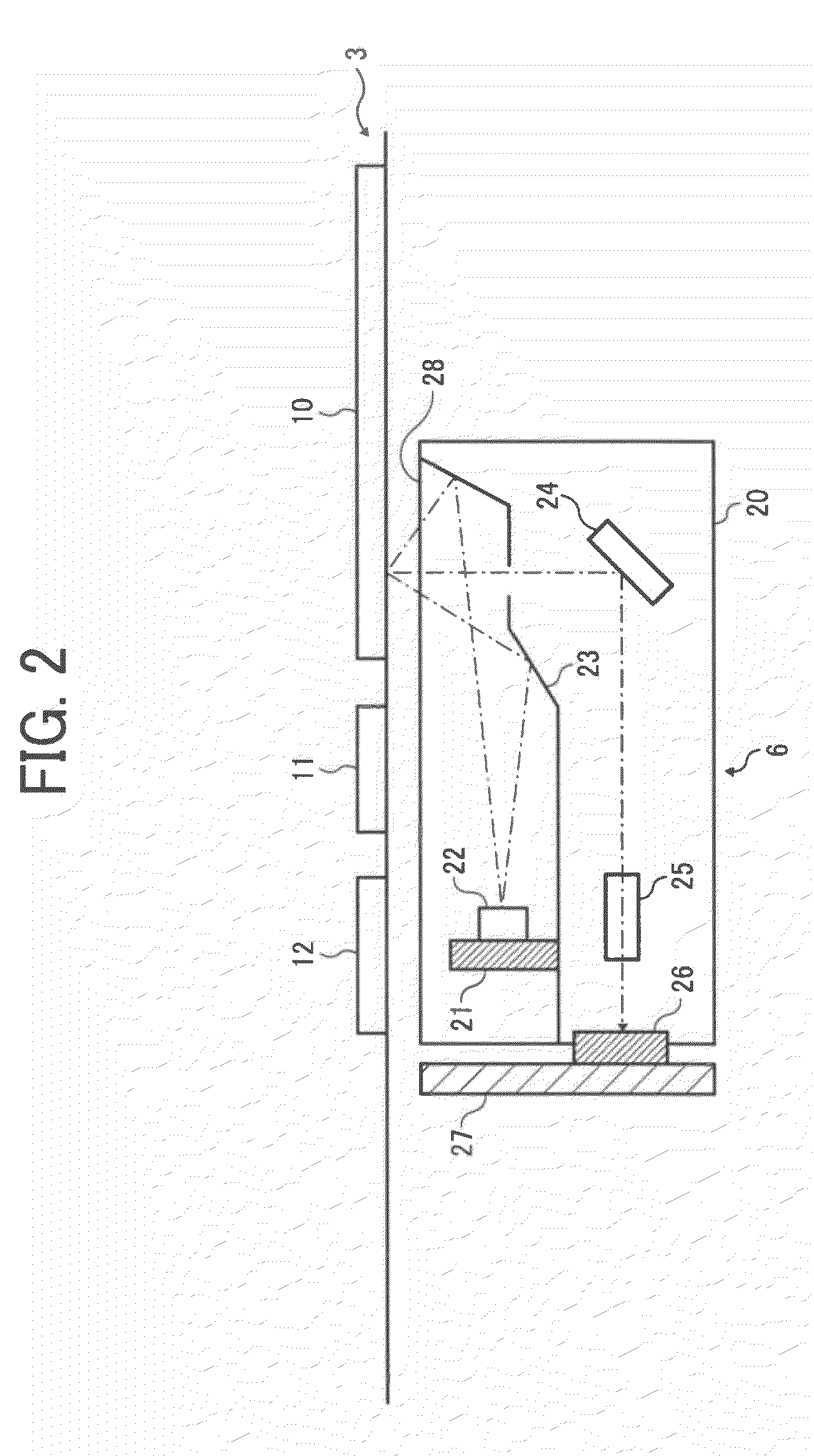
[0042]In FIG. 1, an image scanning apparatus 1 includes an original scanning table 3 on its chassis 2, and the original scanning table 3 includes a contact glass 10 which is a transparent original table (FIG. 2). An openable and closable original press plate 4 is located above the original scanning table 3 and presses an original G set on the original scanning table 3 so as to contact the original G to the contact glass 10.

[0043]An ADF (Auto Document Feeder) 5 is located above the left side of the chassis 2 in FIG. 1, and an image scanning unit 6 is movably located in a horizontal (sub-scanning) direction indicated by an arrow as a scanning direction in FIG. 1 below the original scanning table 3 inside the chassis 2.

[0044]The ADF 5 includes an original table plural originals G are placed on, an original detector detecting whether there is an original G on the original...


PUM


Abstract

An image scanning apparatus, including a contact glass having an original to be scanned on; a light source including plural dotted light-emitting elements linearly arrayed in a main scanning direction and emitting scanning light to the original; a photoelectric converter photoelectrically converting reflected scanning light from the original to produce line-image data in the main scanning direction; a halation detector receiving the line-image data from the photoelectric converter and detecting whether the line-image data has halation; and a corrector receiving information whether the line-image data has halation and correcting pixel values of all pixels of the line-image data having halation into a predetermined pixel value.

Description

BACKGROUND OF THE INVENTION[0001]1. Field of the Invention[0002]The present invention relates to an image scanning apparatus and an image scanning method, and more particularly to an image scanning apparatus and an image scanning method scanning high-quality images, properly inhibiting halation.[0003]2. Discussion of the Background[0004]In image scanning apparatuses of scanning apparatuses, copiers, complex machines, etc., linear light sources capable of emitting continuous linear reading light to an original to be scanned such as Xe lamps and cold-cathode tube lamps have conventionally been used.[0005]However, these light sources largely vary in light quantity as time passes and have short lives, and are difficult to maintain and expensive.[0006]When the scanning light is emitted to the original to scan while the original is floating from a transparent original table, halation occurs, i.e., the original image density increases (images scanned become white).[0007]Recently, lower-cos...

Claims


Application Information

Patent Timeline
Patent Type & Authority Applications(United States)
IPC IPC(8): H04N1/04
CPCH04N1/02845H04N1/02885H04N2201/0081H04N1/1013H04N1/401H04N1/0303
Inventor INADOME, TAKANORI
Owner RICOH KK
Learn More