This helps you quickly interpret patents by identifying the three key elements:
Problems solved by technology
Method used
Benefits of technology
Benefits of technology
[0020]When employing an in-cylinder direct injection injector, a boost circuit is routinely used in the power circuit. However, as compared to a scheme in which a mixture gas of air and fuel is drawn into the cylinder at the intake stroke, the boost circuit will be handling currents that are about 5 to 20 times greater. As a result, the life of electronic components is reduced accompanied by a rise in the temperature of the circuit as a whole, noise increases, and the structure would require heat dissipation, all of which lead to an increase in costs.
Problems solved by technology
As a result, the life of electronic components is reduced accompanied by a rise in the temperature of the circuit as a whole, noise increases, and the structure would require heat dissipation, all of which lead to an increase in costs.
Further, even with the power circuit shown in FIG. 15, although boost control is effected through the boost switching period t4, since this control is not based on the time from the point at which the boost switch element is interrupted (the current flowing through the boost coil begins to drop) up to the point at which current flow is started (the current flowing through the boost coil begins to rise), it cannot be said that the problems indicated above can be solved adequately.
Method used
Image
Click on the blue label to locate the original text in one second.
Reading with bidirectional positioning of images and text.
Examples
embodiment 1
[0059]Embodiment 1, which employs an internal combustion engine controller (a boost power source device) according to the present invention as a constant-current boost scheme power circuit for an injector, is described using FIG. 1, FIG. 2 and FIG. 3.
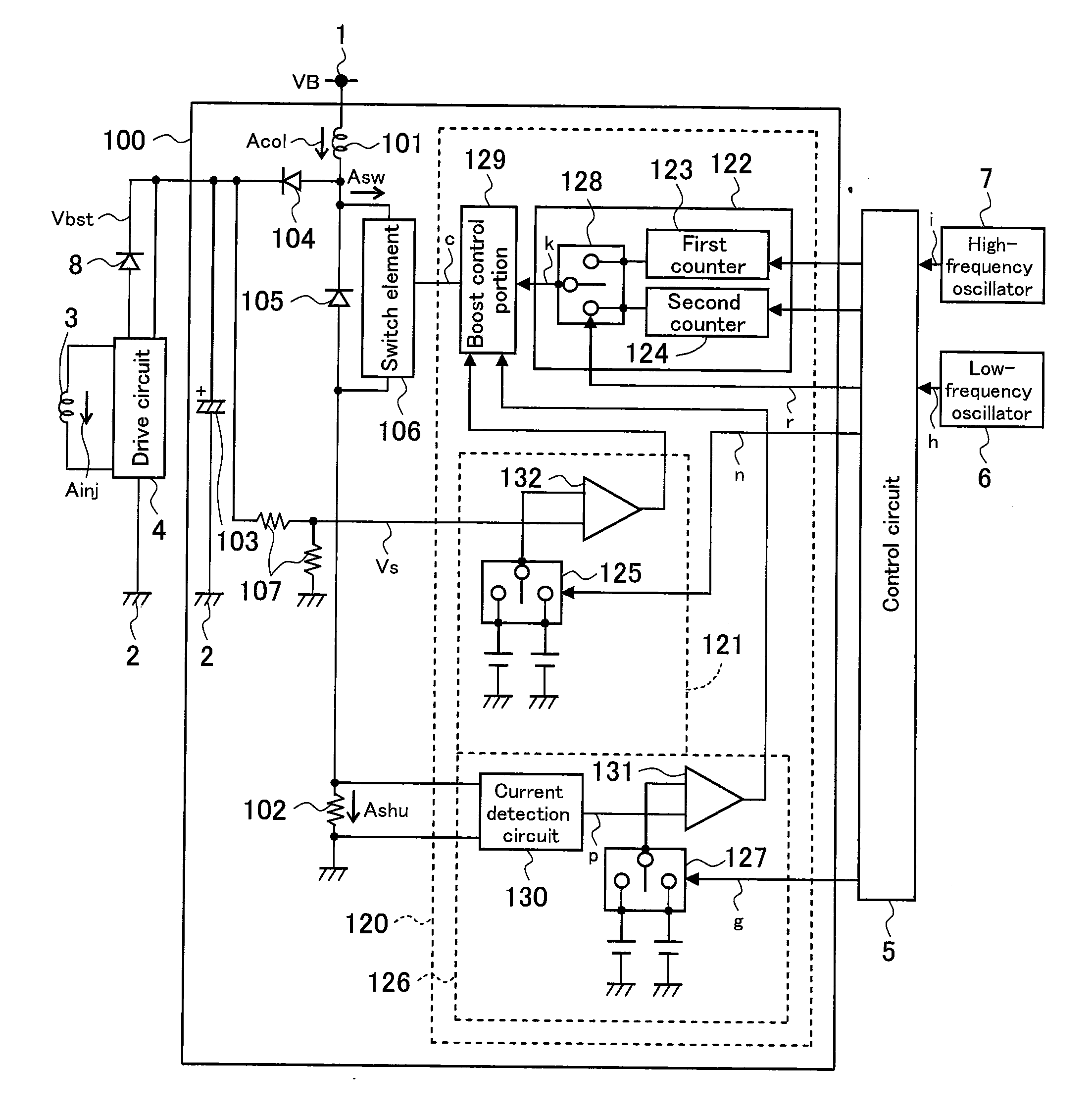
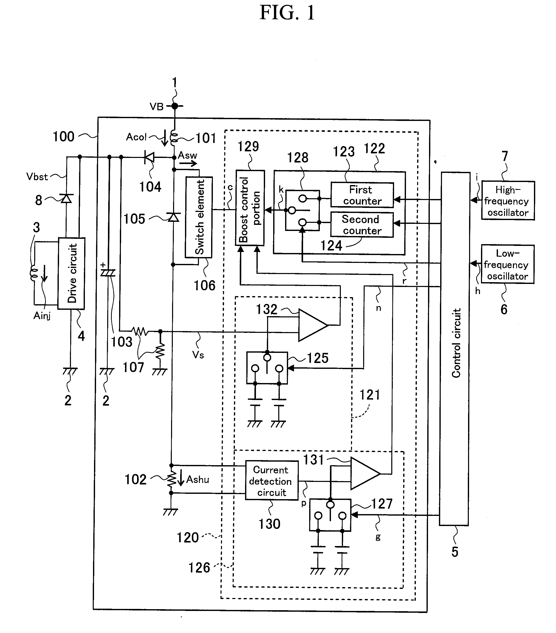
[0060]As shown in FIG. 1, a boost power source device according to the present embodiment comprises a boost circuit 100 to which power is supplied by means of a battery power source 1 and a power source ground 2 thereof. A drive circuit 4 of an injector 3 drives the injector 3 using a boost voltage Vbst that is boosted to a high voltage by the boost circuit 100.
[0061]The boost circuit 100 comprises a boost coil 101 that has an inductive component for boosting a voltage VB of the battery power source 1. Current flow is caused / interrupted with respect to the boost coil 101 by means of a boost switch element 106 that is turned on or off by a boost control signal (c). In other words, the boost switch element 106 performs switching between c...
embodiment 2
[0077]In Embodiment 2, as shown in FIG. 4, there is presented a case in which, in effecting boost control in which boost drive is repeatedly executed by the boost control timing generation portion (set time changing portion) 122, the boost power source device switches between a mode in which a boost coil current minimum value d5 is not allowed to drop to 0 A (i.e., it is dropped so as to remain within the bounds of a predetermined target current) (the mode shown in Embodiment 1), and a mode in which it is dropped to 0 A.
[0078]In Embodiment 2, as shown in FIG. 4, the boost control timing generation portion 122 comprises: the first counter (first time setting portion) 123 that takes an off-time k1, which does not allow the boost coil current minimum value d5 to drop to 0 A, to be the set time Tdown in Embodiment 1 (see FIG. 3) and counts this as a first set time; and a second counter (second time setting portion) 124 that takes an off-time k2, during which the boost coil current minim...
embodiment 3
[0085]In Embodiment 3, there is presented a case in which the boost circuit 100 of the boost power source device drops the boost coil current Aco1 to 0 A, and repeats a boost operation in variable periods using clock signals of the low-frequency oscillator 6 and the high-frequency oscillator 7 shown in FIG. 1.
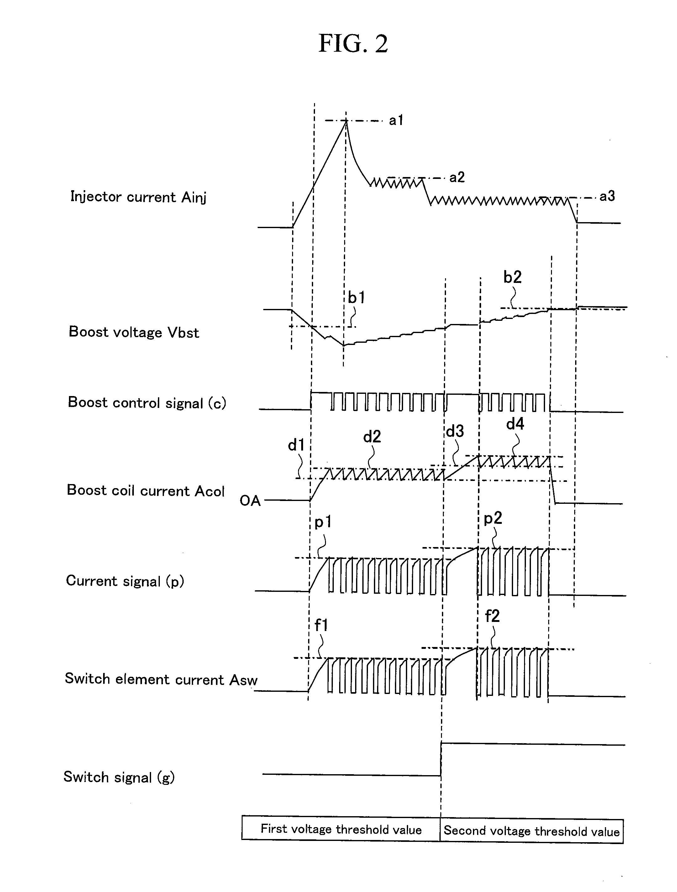
[0086]Specifically, as shown in FIG. 5, a boost basic clock (low-frequency clock) (h) generated by the low-frequency oscillator 6 is taken to be one period for driving the boost switch element 106. If, after the current flow through the boost coil 101 has been started, it is detected by a current detection circuit 130 that the boost coil current Aco1 has reached a preset current value d7, the boost control signal (c) is switched from high to low, and the boost switch element 106 is placed in an off state. Thereafter, the boost coil current Aco1 is held at 0 A, and the boost control signal (c) is again switched from low to high once one cycle of the boost basic clock (h) has ela...
PUM
Abstract
There is provided an internal combustion engine controller that realizes a reduction in maximum current value and current regulation without sacrificing boost performance. An internal combustion engine controller 100 comprises: a boost coil 101 configured to boost a voltage VB of a battery power source; a boost switch element 106 configured to switch between causing a current to flow and stopping a current from flowing through the boost coil 101; and a current detection portion 126 configured to detect a current flowing through the boost switch element 106, wherein boost control is effected by repeating the switching of the switch element, the voltage boosted at the boost coil 101 is charged to a boost capacitor 103 via a diode 104, and, during the boost control, the internal combustion engine controller 100 makes the boost switch element 106 stop the current flowing through the boost coil 101 when the detected current reaches a switching stop current value and, after a predetermined set time Tdown has elapsed from the point at which current flow is stopped, makes the boost switch element 106 cause a current to flow through the boost coil 101.
Description
BACKGROUND OF THE INVENTION[0001]1. Field of the Invention[0002]The present invention relates to an internal combustion engine controller, and more particularly to an internal combustion engine controller, such as a power source device for an in-cylinder direct injection injector of a vehicular internal combustion engine, etc., suitable for use in driving a load using a high voltage obtained by boosting the voltage of a battery power source.[0003]2. Background Art[0004]As an internal combustion engine that runs on gasoline, diesel or the like, there is known an internal combustion engine of an in-cylinder direct injection scheme that injects fuel directly into the cylinder at the compression stroke by means of an injector (fuel injection valve) in order to improve fuel economy. In an internal combustion engine of the in-cylinder direct injection scheme, stratified combustion can be achieved where atomized fuel is present only around the spark plug to establish combustion, and the ai...
Claims
Application Information
Patent Timeline
Application Date:The date an application was filed.
Publication Date:The date a patent or application was officially published.
First Publication Date:The earliest publication date of a patent with the same application number.
Issue Date:Publication date of the patent grant document.
PCT Entry Date:The Entry date of PCT National Phase.
Estimated Expiry Date:The statutory expiry date of a patent right according to the Patent Law, and it is the longest term of protection that the patent right can achieve without the termination of the patent right due to other reasons(Term extension factor has been taken into account ).
Invalid Date:Actual expiry date is based on effective date or publication date of legal transaction data of invalid patent.

