Excitation circuit for electromagnetic flowmeter, and electromagnetic flowmeter

Active Publication Date: 2019-09-19
YAMATAKE HONEYWELL CO LTD
View PDF0 Cites 0 Cited by
  • Summary
  • Abstract
  • Description
  • Claims
  • Application Information

AI Technical Summary

Benefits of technology

[0026]According to an embodiment of the present disclosure, the constant current circuit is not supplied with the high excitation voltage and makes only the current of the low excitation voltage constant. Thus, heat generation by the transistor, such as a power MOSFET, of the constant current circuit caused by application of the high excitation voltage according to the related art can be prevented, and heat generation by the power transistor can be reduced.
[0027]Thus, it is not necessary to use a large ra

Problems solved by technology

Thus, it is difficult to stably sample the flow rate signal, and a measurement error in the value of the flow rate increases.
However, increasing the high excitation voltage VexH causes an increase in drain-source voltage Vds of the power MOSFET Q52 of the constant current circuit CCS in FIG. 5 and an increase in heat generation by the power MOSFET Q5

Method used


Image

  • Excitation circuit for electromagnetic flowmeter, and electromagnetic flowmeter
  • Excitation circuit for electromagnetic flowmeter, and electromagnetic flowmeter
  • Excitation circuit for electromagnetic flowmeter, and electromagnetic flowmeter

Examples


first embodiment

Advantages of First Embodiment

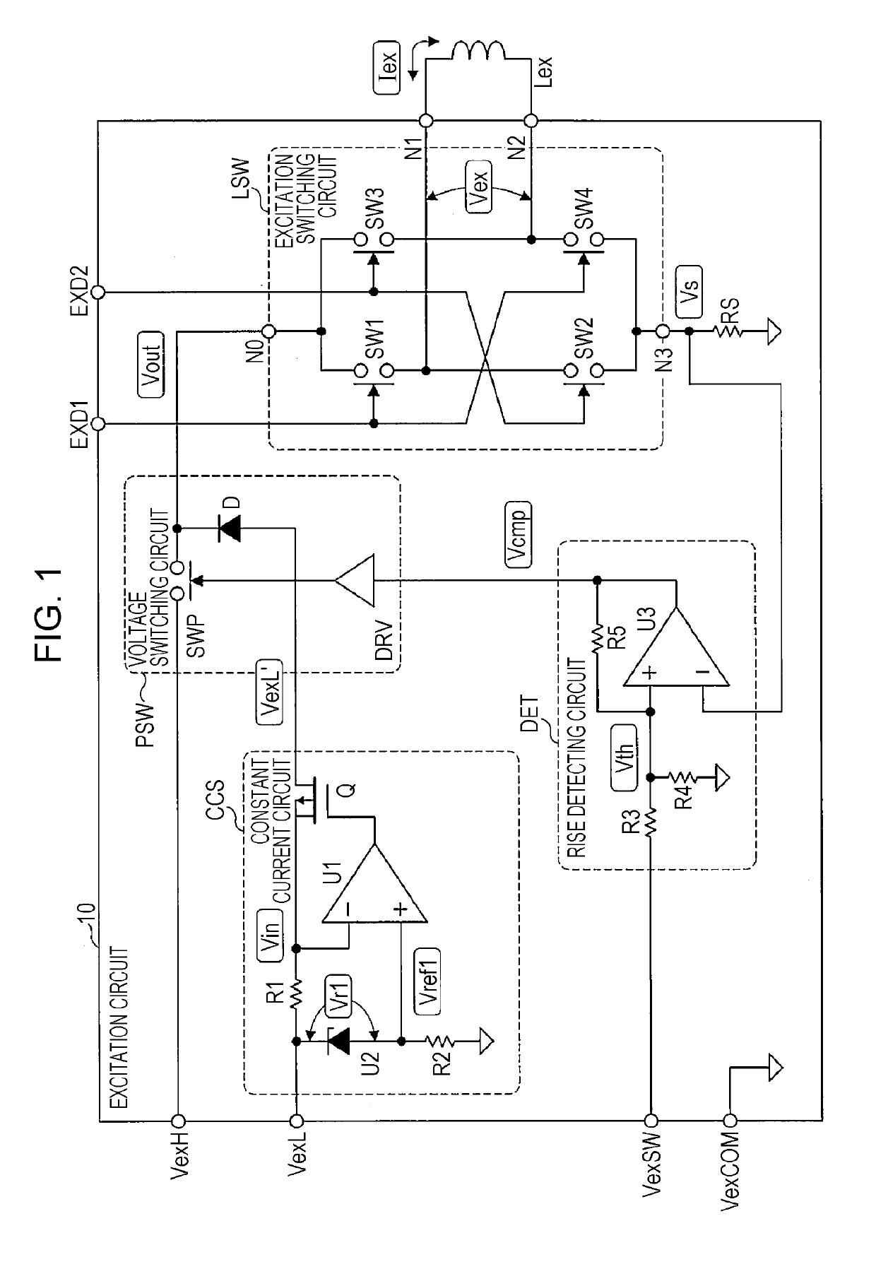
[0073]As described above, in the first embodiment, the voltage switching circuit PSW applies the high excitation voltage VexH to the excitation switching circuit LSW during the period from the excitation period starting point to the rise point in the excitation period, and applies the low excitation voltage VexL lower than the high excitation voltage VexH to the excitation switching circuit LSW during the period from the rise point to the excitation period ending point. The constant current circuit CCS makes the current of the low excitation voltage VexL to be input from the power supply circuit 11 to the voltage switching circuit PSW constant.

[0074]Accordingly, the constant current circuit CCS is not applied with the high excitation voltage VexH, and makes only the current of the low excitation voltage VexL constant. Thus, heat generation by the transistor Q, formed of a power MOSFET or the like, of the constant current circuit CCS caused by applicatio...

second embodiment

Advantages of Second Embodiment

[0087]As described above, in the second embodiment, the constant current circuit CCS may include the transistor Q including an input terminal supplied with the low excitation voltage VexL and an output terminal connected to the voltage switching circuit PSW; and the operational amplifier U1 that compares the reference voltage Vref2 higher than the ground potential VexCOM by the constant voltage Vr2 with the detected voltage Vs higher than the ground potential VexCOM by the voltage generated by the resistance element RS in accordance with the excitation current Iex and that controls the transistor Q on the basis of an obtained result of the comparison.

[0088]Accordingly, the excitation current Iex is made constant on the basis of the ground potential VexCOM, which makes it possible to stably make the current of the low excitation voltage VexL constant even when the value of the low excitation voltage VexL fluctuates. Compared with the constant current ci...


PUM


Abstract

A voltage switching circuit applies a high excitation voltage to an excitation switching circuit during a period from an excitation period starting point to a rise point in an excitation period, and applies a low excitation voltage lower than the high excitation voltage to the excitation switching circuit during a period from the rise point to an excitation period ending point in the excitation period. A constant current circuit makes the current of the low excitation voltage to be input from a power supply circuit to the voltage switching circuit constant.

Description

CROSS-REFERENCE TO RELATED APPLICATIONS[0001]The present application is based on and claims priority to Japanese Application No. 2018-045393, filed Mar. 13, 2018, the entire contents of which are incorporated herein by reference.BACKGROUND DISCLOSURE1. Field Disclosure[0002]The present disclosure relates to an electromagnetic flowmeter that measures the flow rate of a fluid in various process systems, and an excitation circuit that supplies an excitation current to an excitation coil of the electromagnetic flowmeter.2. Description of the Related Art[0003]An electromagnetic flowmeter typically includes an excitation coil that generates a magnetic field in a direction perpendicular to a flow direction of a fluid flowing in a measuring pipe, and a pair of detecting electrodes disposed in the measuring pipe in a direction orthogonal to the magnetic field generated by the excitation coil. Such an electromagnetic flowmeter measures the flow rate of a fluid flowing in the measuring pipe by...

Claims


Application Information

Patent Timeline
IPC IPC(8): G01F1/60G01F1/58
CPCG01F1/588G01F1/60G01F1/586
Inventor MOMOSE, OSAMUMAMADA, KOUICHI
Owner YAMATAKE HONEYWELL CO LTD
Why Eureka
Try Eureka