X-axis reciprocating vibration motor for mixing barrel

A vibrating motor and mixing tank technology, applied in the field of vibrating motors and X-axis reciprocating vibrating motors, can solve problems such as easy accumulation of dust

Active Publication Date: 2021-05-14
JINAN SINOFLON NEW MATERIAL CO LTD
View PDF4 Cites 0 Cited by
  • Summary
  • Abstract
  • Description
  • Claims
  • Application Information

AI Technical Summary

Problems solved by technology

[0003] The technical problem to be solved in the present invention is to provide an X-axis reciprocating vibrating motor for the mixing tank, o

Method used


Image

  • X-axis reciprocating vibration motor for mixing barrel
  • X-axis reciprocating vibration motor for mixing barrel
  • X-axis reciprocating vibration motor for mixing barrel

Examples


Embodiment 1

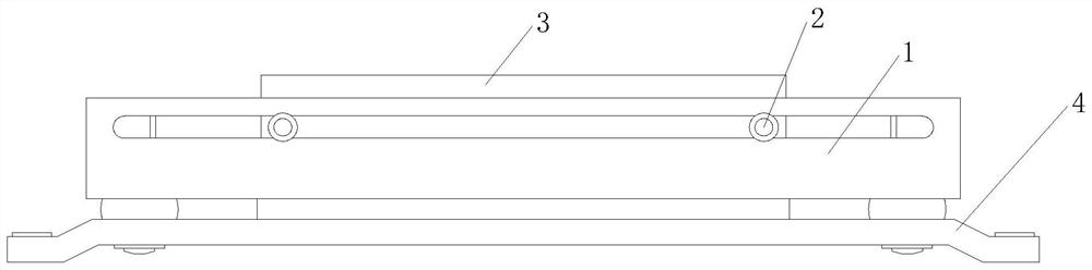
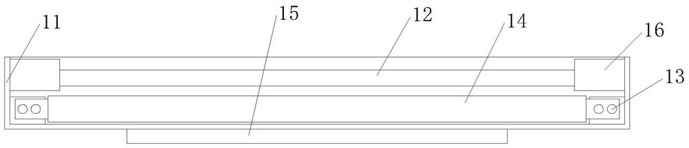
[0026] Such as Figure 1-2 As shown, the present invention provides an X-axis reciprocating vibration motor for a mixing tank, including an electromagnet mechanism 1, the electromagnet mechanism 1 is connected with a permanent magnet 3 through a sliding shaft 2, and the sliding shaft 2 is fixedly installed on On the side of the permanent magnet 3, the bottom of the electromagnet mechanism 1 is provided with a base 4, the electromagnet mechanism 1 includes a casing 11, and a side chute 12 is dug through on the side panel of the casing 11, and the sliding shaft rod 2 is slidably arranged on In the side chute 12 , the inner two ends of the casing 11 are respectively connected with the two ends of the electromagnet body 14 through the mounting base 13 , and the bottom surface of the casing 11 is fixedly mounted with a welding surface 15 .

[0027] In this embodiment, through the magnetic interaction between the designed permanent magnet 3 and the electromagnet body 14, the present...

Embodiment 2

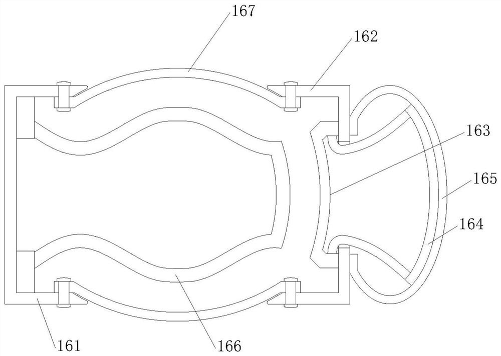
[0029] Such as image 3 As shown, on the basis of Embodiment 1, the present invention provides a technical solution: the buffer 16 includes a welding seat 161, one side of the welding seat 161 is provided with a moving cover 162, and the middle of the moving cover 162 is fixedly welded with an elastic frame 163, one end of the supporting leg of the elastic frame 163 passes through the movable cover 162 and is fixedly connected to the arc-shaped supporting surface 164, the arc-shaped supporting surface 164 is arranged in the rubber ball 165, and the port of the rubber ball 165 and the moving cover 162 are away from the welding seat 161 One side is sealed and connected, and a rebound frame 166 is provided in the middle of one side of the welding seat 161 close to the moving cover 162 , and a drum ball 167 is provided between the welding seat 161 and the moving cover 162 .

[0030] In this embodiment, the rubber ball 165 is provided so that when the permanent magnet 3 impacts the...

Embodiment 3

[0032] Such as image 3 , 5 As shown, on the basis of Embodiment 1, the present invention provides a technical solution: the rebound frame 166 includes a contact surface b1, the contact surface b1 is a square arc panel, and the inner four corners of the contact surface b1 are provided with mute cotton b2, The mute cotton b2 is an S-shaped square rod, and the mute cotton b2 on the opposite side of the contact surface b1 is symmetrical about the contact surface b1. The outer surface of the contact surface b1 is fixedly bonded with a curved leg b3, and the curved leg b3 is compatible with the elastic The frame 163 is correspondingly arranged.

[0033] In this embodiment, the contact surface b1 is designed to contact the elastic frame 163, so that the displacement pressure on the elastic frame 163 is transmitted to the rebound frame 166. At the same time, the contact surface b1 distributes the force and transmits it to the four mutes. Cotton b2 makes the stress conditions of the...


PUM


Abstract

The invention discloses an X-axis reciprocating vibration motor for a mixing barrel, and relates to the technical field of motors. The X-axis reciprocating vibration motor comprises an electromagnet mechanism, the electromagnet mechanism is in transmission connection with a permanent magnet through a sliding shaft rod, the sliding shaft rod is fixedly installed on the side edge of the permanent magnet, and a base is arranged at the bottom of the electromagnet mechanism; and the electromagnet mechanism comprises a shell, a side edge sliding groove is formed in a side edge panel of the shell in a penetrating mode, the sliding shaft rod is arranged in the side edge sliding groove in a sliding mode, and the two ends of the interior of the shell are connected with the two ends of an electromagnet body through mounting bases correspondingly. Kinetic energy generated when the permanent magnet moves is converted through the designed buffer, so that gas in the buffer can be sprayed out in a high-pressure state, dust in internal gaps can be automatically blown away through the design during use, and the self-cleaning effect is achieved; and the probability of the problems of easy heat generation, power reduction and the like caused by excessive dust accumulation in the shell is reduced.

Description

technical field [0001] The invention relates to a vibration motor, relates to the technical field of motors, in particular to an X-axis reciprocating vibration motor used for a mixing tank. Background technique [0002] In the X-axis reciprocating vibration motor in the prior art, most of its two ends during operation adopt simple shrapnel and spring structures, which only play the role of shock absorption and buffering, and this kind of vibration motor is very easy to use during use. There is a phenomenon that dust enters the interior. Under the disturbance of the stable and balanced internal airflow when the motor is running, the dust cannot be discharged. If there is too much accumulation, it will cause the vibration amplitude to change and other defects. There are improvements. Contents of the invention [0003] The technical problem to be solved in the present invention is to provide an X-axis reciprocating vibrating motor for a mixing tank, one of the purposes of whi...

Claims


Application Information

Patent Timeline
IPC IPC(8): H02K33/18H02K5/24B08B5/02
CPCH02K33/18H02K5/24B08B5/02
Inventor 陈月秋
Owner JINAN SINOFLON NEW MATERIAL CO LTD
Why Eureka
Try Eureka