Lip Seal With Inversion Prevention Feature

a technology of inversion prevention and seals, which is applied in the direction of engine seals, mechanical devices, engine components, etc., can solve the problems of increasing torque and extenuating the problem of highly incompressible materials, and achieve the effects of improving shaft followability, reducing seal torque and increasing thickness

Active Publication Date: 2010-09-30
FREUDENBERG NOK GEN PARTNERSHIP
View PDF34 Cites 21 Cited by
  • Summary
  • Abstract
  • Description
  • Claims
  • Application Information

AI Technical Summary

Benefits of technology

[0003]The present invention is designed to reduce seal torque, the propensity for “bell mouthing” and also provides for improved shaft followability at low temperatures. The dynamic seal includes an annular mounting portion which is capable of being mounted to a casing which surrounds a rotary shaft. The seal includes an axially extending portion extending from the radially inner end of the mounting portion, with a radially extending portion extending inwardly from an end of the axially extending portion. A generally conically shaped seal portion extends from an end of the radially extending portion with the seal portion including a radially inner face provided with a plurality of grooves or ribs and a radially outer face having a special bead defining a region of increased thickness. The bead acts as an integral spring to control the gap between the essentially conical portion of the seal and the shaft as well as a means for counteracting the “bell mouthing” propensity of the seal portion. The bead can have different shapes including a triangular-cross section or a rounded bead, as well as other configurations which are deemed to be appropriate. The bead is positioned slightly away from the edge of the lip to provide a sufficient lip “lay-down” to properly engage the hydrodynamic pumping features, which would normally be located on the lip contact are between the edge of the seal and the bead. The flexibility of the axially extending portion of the seal provides an improvement in the shaft followability due to the generally cylindrical shape of the axially extending portion having lower bending stiffness. Therefore, if the material of the seal does not have sufficient intrinsic elasticity, making the axially extending portion of the seal in a generally cylindrical shape improves the overall shaft followability. The length and the wall thickness of the cylindrical portion allow one to control the degree of flexibility to match the application requirements.

Problems solved by technology

Three major problems associated with seals designed to have substantial contact areas between the shaft and the lip of the seal are “bell mouth,” the shaft followability at low temperatures, and oil carbonization in the pumping grooves due to local temperature rise causing increased torque.
The problem is extenuated for highly incompressible materials, like rubber and PTFE.

Method used


Image

  • Lip Seal With Inversion Prevention Feature
  • Lip Seal With Inversion Prevention Feature
  • Lip Seal With Inversion Prevention Feature

Examples


Embodiment Construction

[0014]The following description of the preferred embodiment(s) is merely exemplary in nature and is in no way intended to limit the invention, its application, or uses.

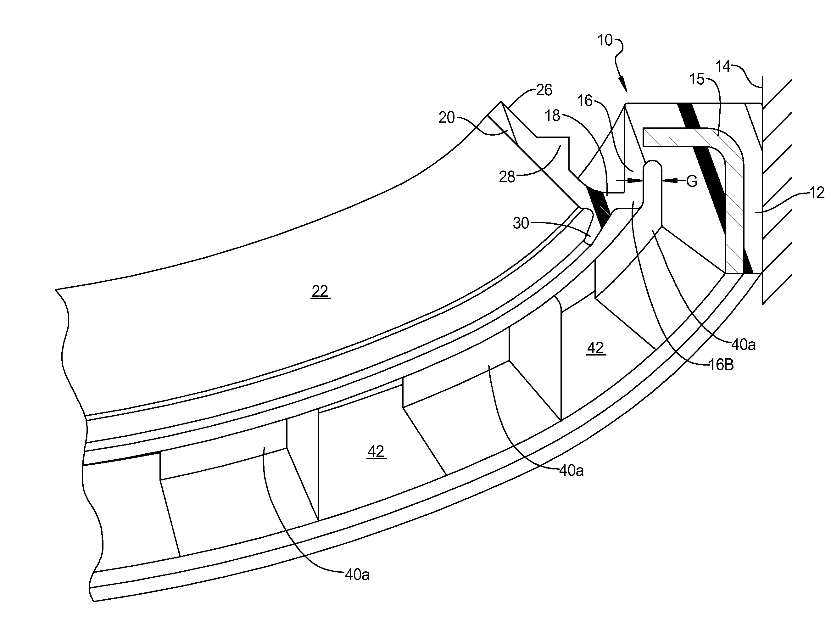
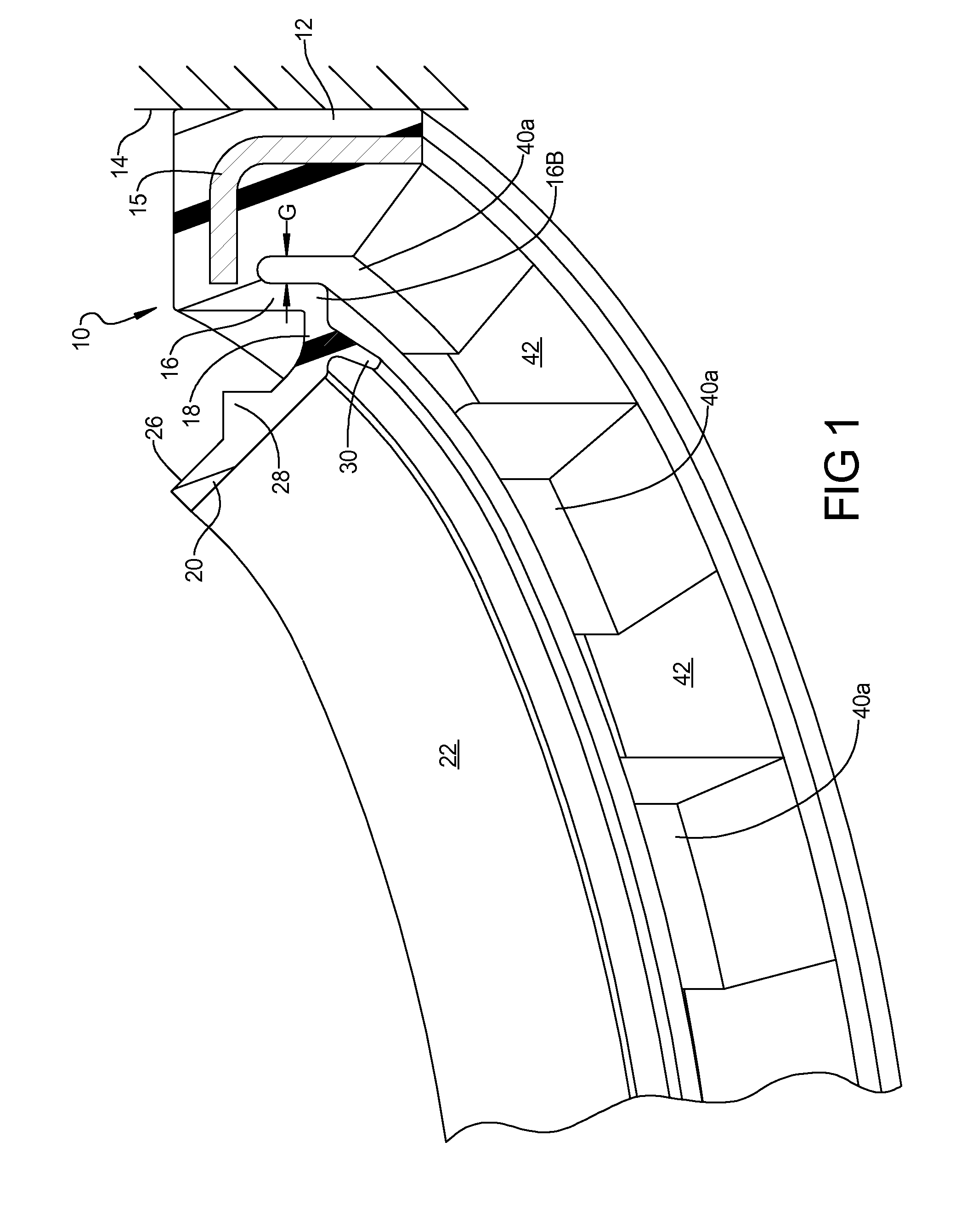
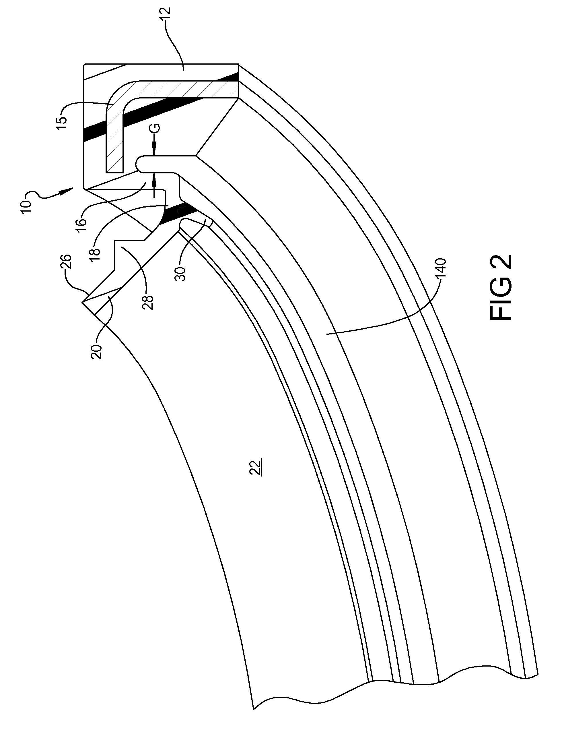
[0015]With reference to FIG. 1, a dynamic seal 10, according to the principles of the present disclosure, will now be described. The dynamic seal 10 includes a mounting portion 12 which is designed to be engaged within a bore of an outer housing 14. It should be noted that the mounting portion 12 can take on many shapes and can include an insert 15 which can be made from metal or plastic or other rigid material and can have an “L” or other cross-sectional shape.

[0016]The dynamic seal 10 includes an axially extending barrel portion 16 extending from a radially inner end 12A of the mounting portion 12. The axially extending barrel portion 16 is preferably generally cylindrical in shape although other shapes, such as conical or a convoluted curve shape, can also be utilized. The dynamic seal 10 includes a radially extend...


PUM


Abstract

A dynamic shaft seal assembly is provided including a dynamic seal for engaging a rotary shaft. The dynamic seal includes a mounting portion that is mounted within a casing and has an axially extending barrel portion extending from a radially inner end of the mounting portion. The axially extending barrel portion terminates in a radially extending leg portion which extends inwardly from an end of the axially extending portion. A generally conically shaped seal portion extends from an end of the radially extending portion and the seal portion includes a radially inner face engaging the shaft and a radially outer face having a stiffening bead integrally formed thereon. The mounting portion defines a bumper spaced from the axially extending barrel portion by a gap distance that is designed to prevent the seal lip from inverting under sustained high pressure or pressure spikes.

Description

FIELD OF THE INVENTION[0001]The present invention relates to “lay-down” dynamic shaft seals, and more particularly, to a dynamic shaft seal design to reduce the seal's torque, propensity for bell mouthing, and for providing improved shaft followability and improved ability to withstand internal excessive pressure or vacuum. The “lay-down” seal for their function rely on hydrodynamic pumping features as opposed to “standard” or “point-contact” seals that rely primarily on the intrinsic ability of some elastomers to pump in properly designed seals.BACKGROUND AND SUMMARY OF THE INVENTION[0002]Rotary shaft seals have been utilized in machinery, the automobile industry, as well as other industries. Three major problems associated with seals designed to have substantial contact areas between the shaft and the lip of the seal are “bell mouth,” the shaft followability at low temperatures, and oil carbonization in the pumping grooves due to local temperature rise causing increased torque. “B...

Claims


Application Information

Patent Timeline
Patent Type & Authority Applications(United States)
IPC IPC(8): F16J15/32
CPCF16J15/322F16J15/32F16J15/3244
Inventor BERDICHEVSKY, ALEXANDERPAWL, RORY S.SCHEIB, PATRICK
Owner FREUDENBERG NOK GEN PARTNERSHIP
Why Eureka
Try Eureka