Plastic cap featuring excellent sealing and venting

a technology of plastic caps and sealing rings, applied in the field of plastic caps, can solve the problems of difficult gas venting, easy deformation of inner rings, and decreased thickness of inner rings, and achieve the effect of convenient venting

Active Publication Date: 2009-08-18
TOYO SEIKAN KAISHA LTD +1
View PDF38 Cites 32 Cited by
  • Summary
  • Abstract
  • Description
  • Claims
  • Application Information

AI Technical Summary

Benefits of technology

[0007]The cap proposed in the above JP-A-2004-224371 is such that when the top panel of the cap is domed due to an increase in the pressure in the container, the end of the inner ring deforms inward being pulled by the coupling portion, the intimate adhesion is lost between the outer surface of the inner ring and the inner surface of the mouth-wall of the container, and the gas is easily vented.
[0008]This cap, however, involves a problem in that the thickness of the inner ring must be decreased so that the inner ring can be easily deformed by being pulled by the coupling portion when the top panel of the cap is domed. That is, the inner ring that is thickly formed possesses a high rigidity and is not easily deformed even when it is pulled by the coupling portion, making it difficult to vent the gas. On the other hand, the inner ring that is thinly formed offers an increased degree of flexibility but causes a decrease in the sealing of the inner ring.
[0010]It is therefore an object of the present invention to provide a plastic cap featuring both excellent sealing and venting.
[0023]According to the present invention, the inner ring is easily deformed upon doming since a slender recessed portion is formed in the inner surface of the inner ring. That is, when the pressure in the container has increased causing the top panel of the cap to be domed (swollen outward), the inner ring is so deformed that an end thereof is directed to the inside. Here, with the recessed portion being formed as described above, distortion such as wrinkles caused by the deformation are absorbed by the recessed portion. As a result, deformation of the inner ring is promoted, the intimate contact decreases between the outer surface of the inner ring and the inner surface of the mouth-wall of the container, and the gas is easily vented. Besides, in the present invention, there is no need of decreasing the thickness of the inner ring; i.e., the inner ring can be deformed upon doming even when the inner ring has a thickness large enough for maintaining a high degree of sealing like that of the conventional caps. Thus, the present invention accomplishes both excellent sealing and excellent venting.

Problems solved by technology

This cap, however, involves a problem in that the thickness of the inner ring must be decreased so that the inner ring can be easily deformed by being pulled by the coupling portion when the top panel of the cap is domed.
That is, the inner ring that is thickly formed possesses a high rigidity and is not easily deformed even when it is pulled by the coupling portion, making it difficult to vent the gas.
As described above, the conventional caps are not capable of accomplishing both the sealing and the venting of the caps.

Method used


Image

  • Plastic cap featuring excellent sealing and venting
  • Plastic cap featuring excellent sealing and venting
  • Plastic cap featuring excellent sealing and venting

Examples


examples

[0055]Effects of the invention will now be described by way of the following Experiments. Here, however, the invention is in no way limited to the Experiments only.

Cap A (Present Invention):

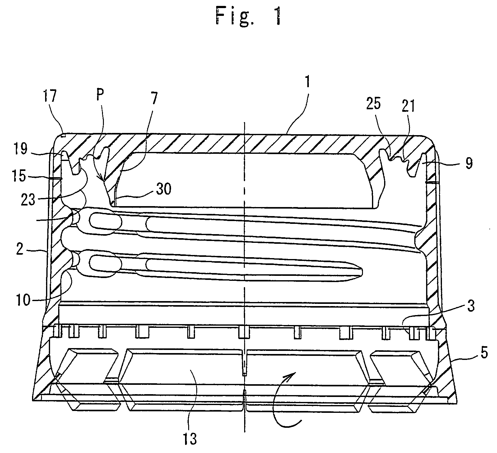
[0056]There was formed by compression molding a cap having the same shape as that of FIG. 1 and that could be wrapped and tightened to the mouth of the container of a nominal diameter of 28 mm.

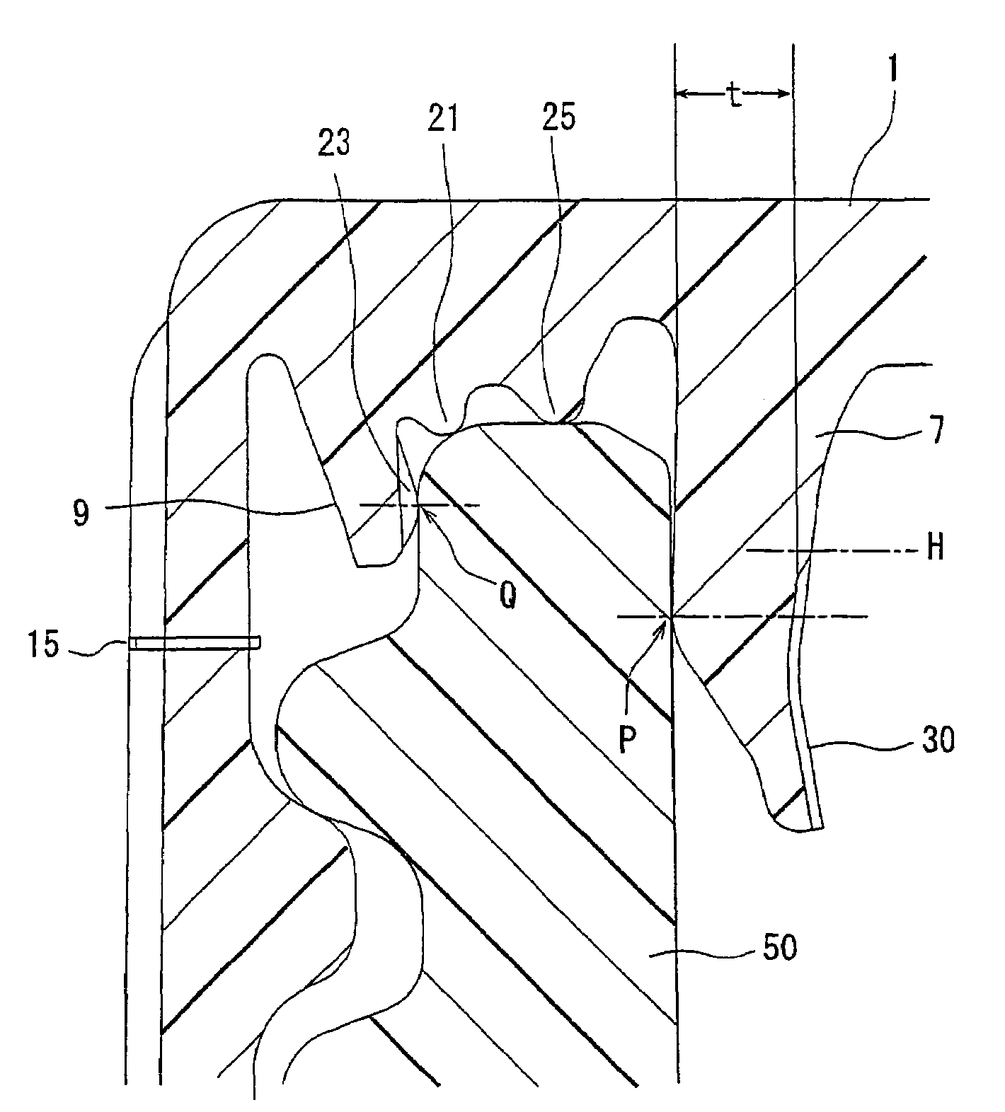
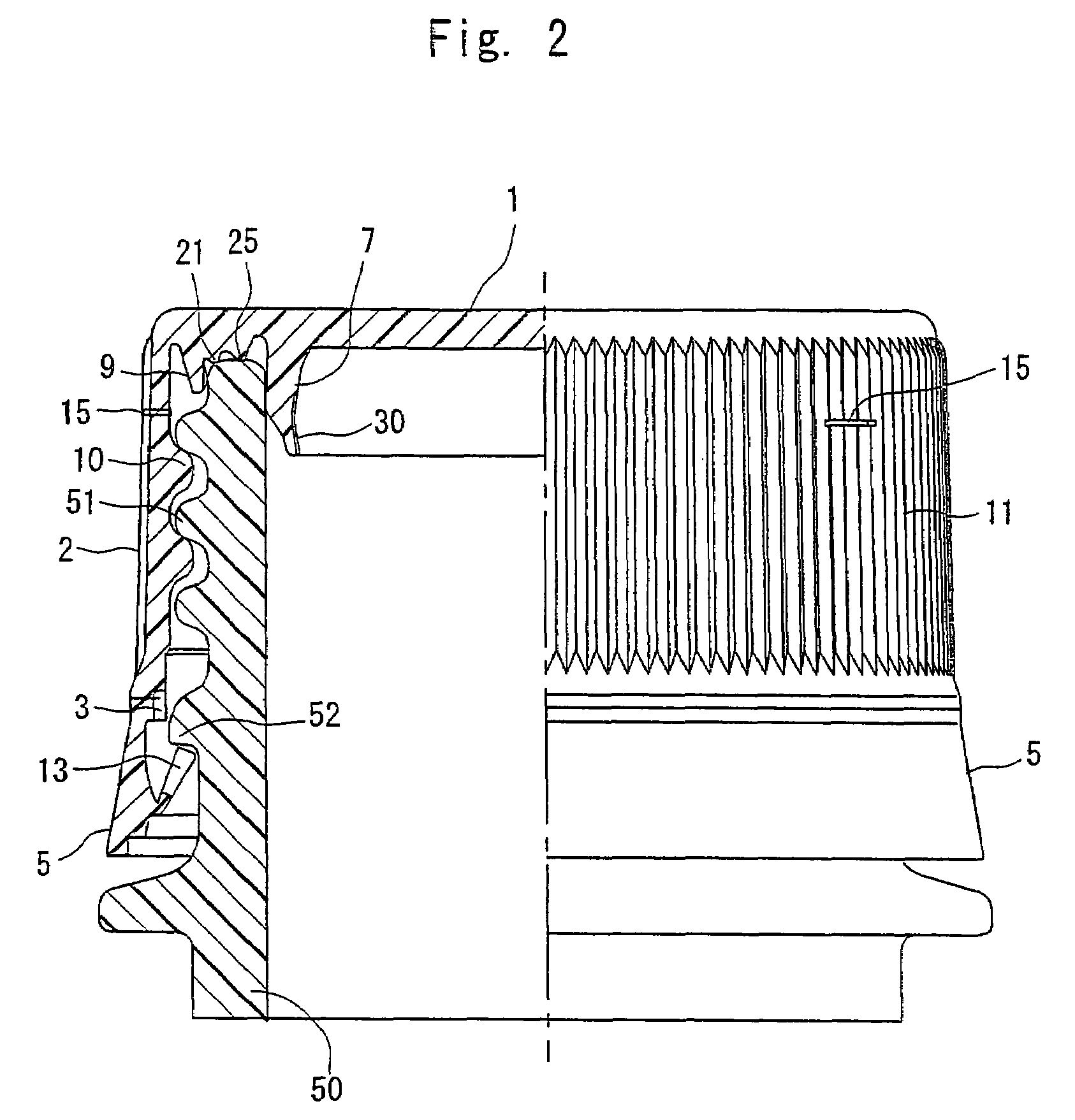
[0057]One recessed portion 30 (width w of 3 mm) was formed. The distance between the upper end position H of the recessed portion 30 and the seal point P was 0.4 mm. The root portion of the inner ring 7 forming the recessed portion 30 therein possessed a thickness of 1.1 mm, and the recessed portion 30 possessed a depth of 0.1 mm.

Cap B (Present Invention):

[0058]A cap B was formed in quite the same manner as the cap A but forming six recessed portions 30 in the inner surface of the inner ring 7 maintaining an equal distance, each recessed portion 30 having a width w of 1 mm, a depth of 0.15 mm and running ov...

experiment 1 (

Drop Impact Test):

[0060]500-Milliliter PET bottles were filled with a 1% orthotolidine aqueous solution heated at 87° C., wrap-tightened with caps A to C, cooled with the shower, and preserved at normal temperature for 24 hours to prepare test samples on which the caps A to C were wrap-tightened, each in a number of 10.

[0061]Hypochlorous acid was dropped on the caps of the test samples each of a number of 10 prepared above. The test samples in an inverted state were dropped in a vertical direction on a steel cylindrical member of which the upper surface had been inclined at 10° from a height of 100 cm. Thereafter, the test samples were immersed in the hypochlorous acid diluted with the tap water of 5° C. for 24 hours.

[0062]There was recognized no change in the color of the 1% orthotolidine aqueous solution in the bottles of the test samples each of a number of 10 to which the caps A and B of the invention and the caps C of Comparative Example had been wrap-tightened. That is, the se...

experiment 2 (

Vent Test):

[0063]500-Milliliter PET bottles were filled with the tap water heated at 87° C., wrap-tightened with caps A to C, cooled with the shower, and preserved at normal temperature for 24 hours to prepare test samples on which the caps A to C were wrap-tightened, each in a number of 10.

[0064]The test samples each of a number of 10 prepared above were held in a water vessel, and a needle having a nitrogen injection hole was stubbed into the top panels of the caps. Nitrogen was injected through the injection hole at a rate of 0.034 MPa / sec to measure the pressure in the bottle at which the seal between the bottle and the cap was broken and nitrogen leaked out. Here, however, the measurement was taken in a state where the test samples were held in a casing such that the bottles were not broken by the pressure of the gas.

[0065]In the test samples of the number of 10 wrap-tightened with the cap A of the invention, nitrogen leaked at an average pressure of 0.78 MPa and the gas could ...


PUM

PropertyMeasurementUnit
widthaaaaaaaaaa
thicknessaaaaaaaaaa
depthaaaaaaaaaa

Abstract

A plastic cap comprising a top panel and a skirt hanging down from the peripheral edge of the top panel, the inner surface of the top panel forming an inner ring that forms a seal upon coming into intimate contact with the inner surface of the wall of the mouth of a container, and the inner surface of skirt forming a screw thread that comes into engagement with a screw thread formed on the outer surface of the wall of the mouth of the container, wherein a slender recessed portion is formed in a number of at least one in the inner surface of said inner ring extending upward from an end thereof. The cap features both excellent sealing and excellent venting.

Description

BACKGROUND OF THE INVENTION[0001]1. Field of the Invention[0002]The present invention relates to a plastic cap of the type of screw engagement. More specifically, the invention relates to a plastic cap of the type of screw engagement in which an inner ring is formed on the inner surface of the top panel of the cap for forming a seal upon coming in intimate contact with the inner surface of the mouth-wall of the container to accomplish a favorable sealing relying upon the inner ring while providing venting in case the pressure in the bottle is elevated.[0003]2. Description of the Related Art[0004]Plastic caps of the type of screw fitted to the mouth-wall of the container relying on the screw engagement have been widely used, for example, for beverage containers. Usually, an inner ring is formed on the inner surface of the top panel of the cap, and an upper end portion of the mouth-wall of the container enters into between a skirt of the cap and the inner ring in a state where the cap...

Claims


Application Information

Patent Timeline
Patent Type & Authority Patents(United States)
IPC IPC(8): B65D53/06
CPCB65D41/325B65D51/1661B65D41/3428B65D41/00B65D41/16
Inventor OOKA, SHINJITOMITAKA, YUJIAIHARA, MANABUMATSUMOTO, SHINYA
Owner TOYO SEIKAN KAISHA LTD
Why Eureka
Try Eureka