

Electronic device and method for operating screen
a technology of electronic devices and screens, applied in the direction of electric digital data processing, instruments, computing, etc., can solve the problems of extremely common operation errors and limited size of touch screens
- Summary
- Abstract
- Description
- Claims
- Application Information
AI Technical Summary
Benefits of technology
Problems solved by technology
Method used
Image

Examples
first embodiment
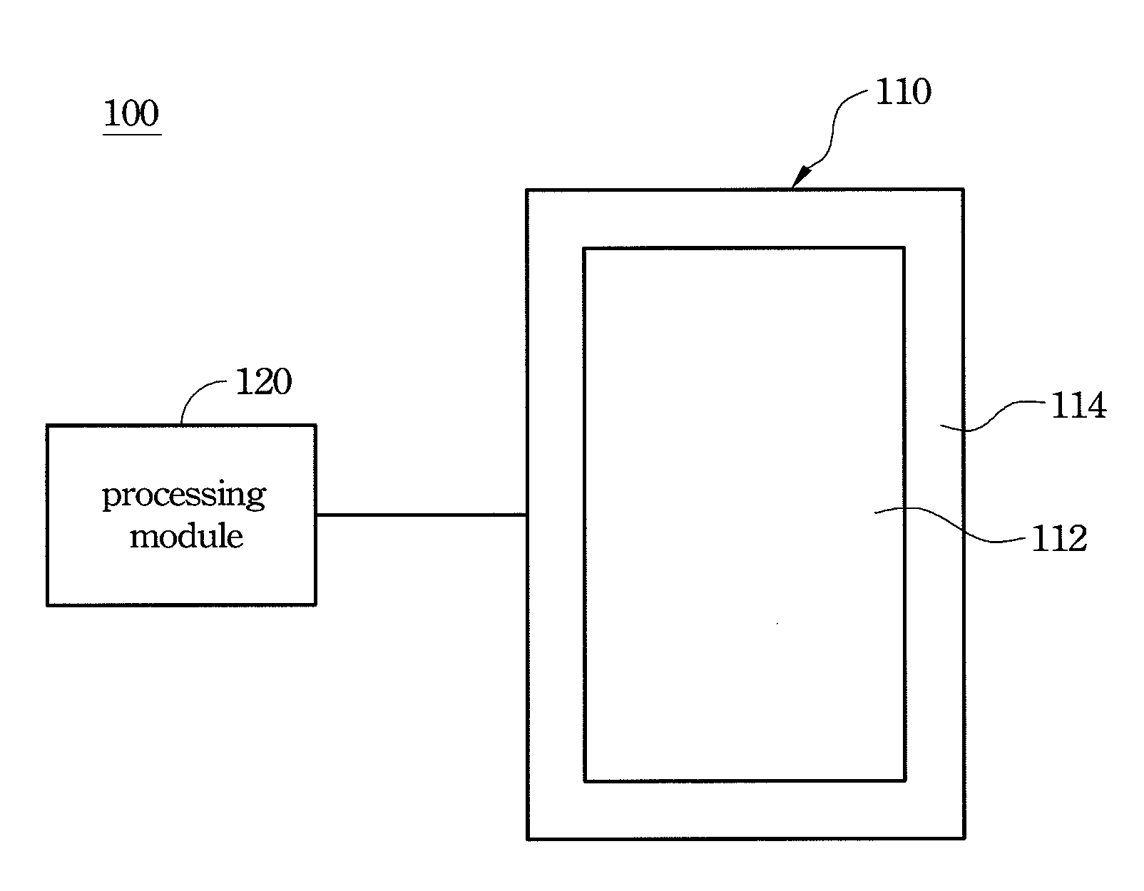
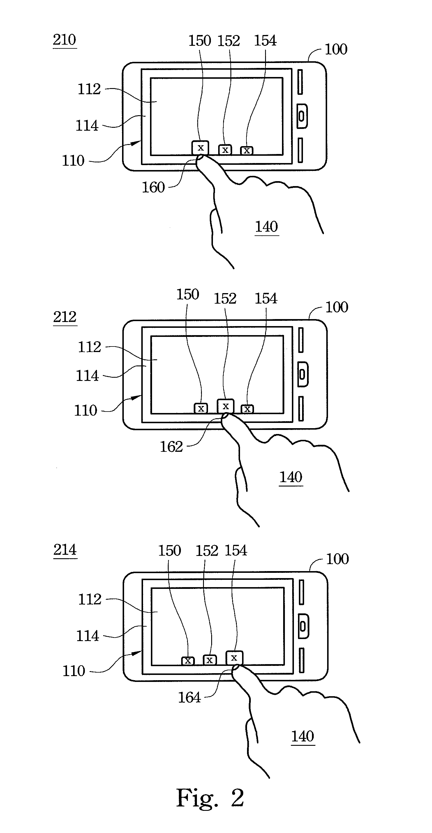
[0032]As shown in FIG. 1, the first sensing signal is generated when a designator 140 controls a pointer on the non-display area 114. The processing is module 120 commands the display area 112 to display a menu based on the first sensing signal. The menu has at least one the item. The screen 110 presets at least one trigger position corresponding to a place that the item is displayed. When the designator 140 is moved from the non-display area 114 to the display area 112, the second sensing signal is generated for confirming the user's motion. When the designator 140 is moved on the display area 112 and touches the trigger position, the third sensing signal is generated. When receiving the first, second and third sensing signals that are sequentially generated by the screen 110, the processing module 120 opens the user interface corresponding to the item in the display area 112.
[0033]As shown in FIG. 3, in the operating state 220, the first sensing signal is generated when the design...
second embodiment
[0034]As shown in FIG. 1, the first sensing signal is generated when a designator 140 controls a pointer to move to the non-display area 114. The processing module 120 commands the display area 112 to display a menu based on the first sensing signal. The menu has at least one the item. When the designator 140 is moved from the non-display area 114 to the display area 112, the second sensing signal is generated. Then, the third sensing signal is generated when the designator 140 drags the item on the display area 112 and then moves away from the screen 110. When receiving the first, second and third sensing signals that are sequentially generated by the screen 110, the processing module 120 opens the user interface corresponding to the item in the display area 112.
[0035]As shown in FIG. 4, in the operating state 230, the first sensing signal is generated when the designator 140 touches the non-display area 114; the display area 112 renders a menu containing items 150 and 154. Then, t...
third embodiment
[0036]As shown in FIG. 1, the first sensing signal is generated when a designator 140 controls a pointer on the non-display area 114. The processing module 120 commands the display area 112 to display a menu based on the first sensing signal. The menu has at least one the item. Then, the second sensing signal is generated when the designator 140 is moved from the non-display area 114 to the display area 112. Then, the third sensing signal is generated when the designator 140 continuously drags the item on the display area 112 and changes directions of dragging the item. When receiving the first, second and third sensing signals that are sequentially generated by the screen is 110, the processing module 120 opens the user interface corresponding to the item in the display area 112.
[0037]In practice, when the designator 140 drags the item in a first direction and turns to a second direction, and when an included angle between the first and second directions is larger than 90°, the thi...
PUM
 Abstract
Description
Claims
Application Information