Turbomolecular pump device and controlling device thereof

Active Publication Date: 2010-09-30
SHIMADZU CORP
View PDF3 Cites 28 Cited by
  • Summary
  • Abstract
  • Description
  • Claims
  • Application Information

AI Technical Summary

Benefits of technology

[0014]In the present invention a long and thin rod-shaped heating resistive member is disposed routed into a corner portion within a case, thereby

Problems solved by technology

Consequently, when a braking resistance is disposed within the power supply device case, the

Method used


Image

  • Turbomolecular pump device and controlling device thereof
  • Turbomolecular pump device and controlling device thereof
  • Turbomolecular pump device and controlling device thereof

Examples


Embodiment Construction

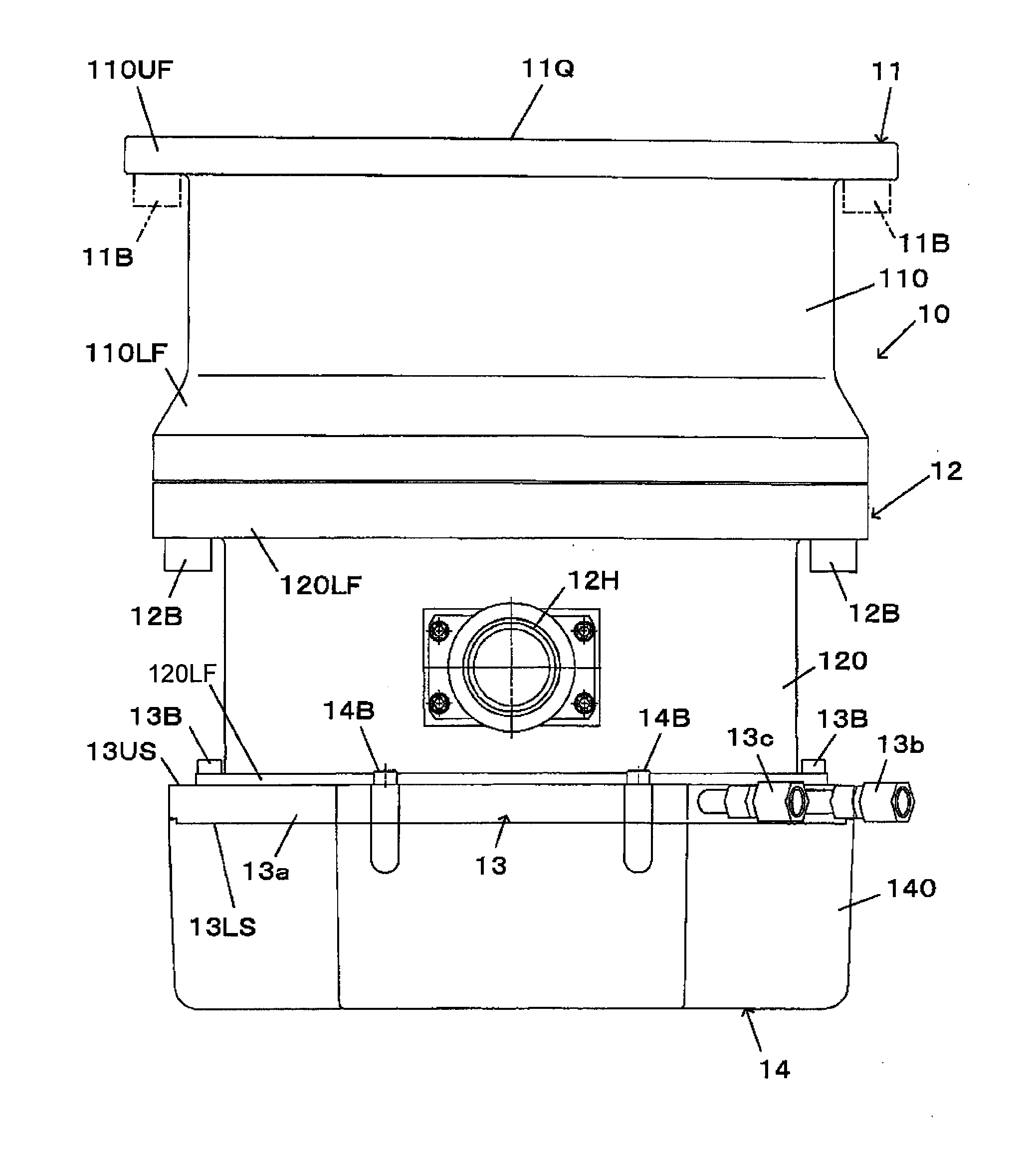
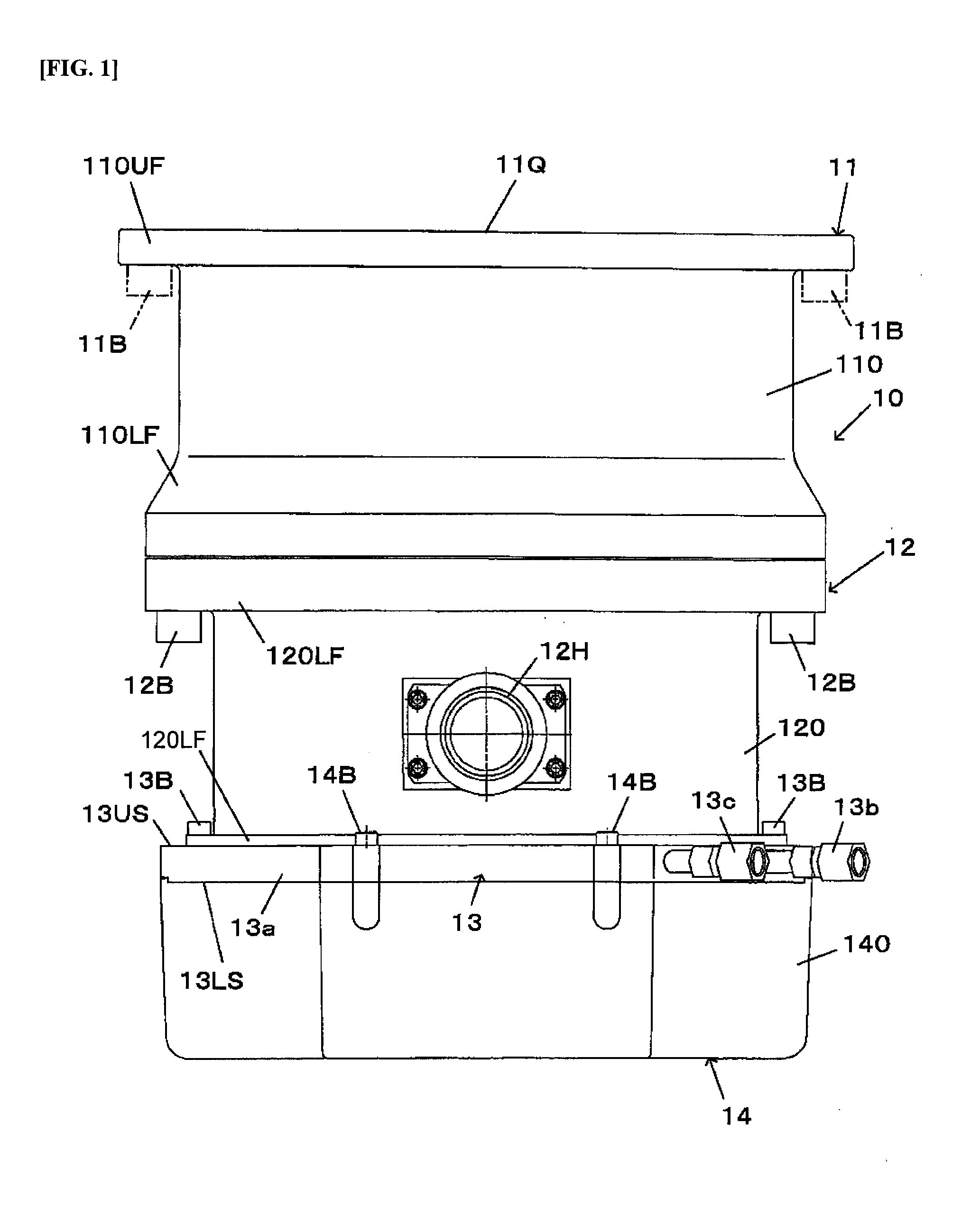
[0027]A turbomolecular pump device 10 according to the present invention will be explained in reference to FIG. 1 through FIG. 10. The turbomolecular pump device exhausts air molecules through the high-speed rotation of a rotary vein relative to a static vein through a rotor on which the rotary vein is formed, driven rotationally by a motor. This type of turbomolecular pump device can be connected to a variety of vacuum processing devices for use.

[0028]FIG. 1 illustrates an outside view of a turbomolecular pump device 10 that is one example of embodiment according to the present invention. The turbomolecular pump device 10 comprises a pump main unit 11 that performs a vacuum exhaust, a base 12 (also “exhaust portion”), a cooling device 13, and a controlling device 14 (hereinafter termed a “power supply device”) for controlling the driving of the pump main unit 11. The pump main unit 11 is a of a well-known structure, and thus the detailed description thereof is omitted; however, typ...


PUM


Abstract

A turbomolecular pump having a pump main unit having, at least, a rotary vein provided on a rotor, a static vein for working in cooperation with the rotary vein to perform a vacuum exhaust, and a motor for driving the rotor, comprising: a controlling device that includes a motor driving circuit for converting into thermal energy, in a regenerative braking resistance, the regenerative electric current that is produced at the time of regeneratively driving the motor; and a cooling device for cooling the controlling device. A rod-shape heating resistive element is used as the regenerative braking resistance, where this resistive heating element is routed along the inner peripheral surface of an end portion 14a of the controlling device case that contacts the cooling device.

Description

CROSS REFERENCE TO RELATED APPLICATIONS[0001]The present application claims priority under 35 U.S.C. §119 to Japanese Patent Application No. 2009-087036, filed Mar. 31, 2009, which is incorporated herein by reference.FIELD OF TECHNOLOGY[0002]The present invention relates to a turbomolecular pump device and to a controlling device thereof.BACKGROUND OF THE INVENTION[0003]A turbomolecular pump device exhausts air molecules through the high-speed rotation of a rotary vane relative to a static vane through a rotor, wherein a rotary vein is formed, being driven rotationally by a motor. This type of turbomolecular pump device is connected to a variety of vacuum processing devices for use. When the rotor is stopped in a turbomolecular pump, regenerative electric power from the regenerative driving of the motor is converted into heat energy in regenerative braking resistances to enhance the rotor stopping performance (in, for example, Japanese Unexamined Patent Application Publication 2002-...

Claims


Application Information

Patent Timeline
IPC IPC(8): F04B35/04
CPCF04B35/045F04D19/042F04D25/068F04D29/5813
Inventor NAGANO, YOSHIHIROKOZAKI, JUNICHIRO
Owner SHIMADZU CORP
Why Eureka
Try Eureka