

Touch control click structure
- Summary
- Abstract
- Description
- Claims
- Application Information
AI Technical Summary
Benefits of technology
Problems solved by technology
Method used
Image

Examples
second embodiment
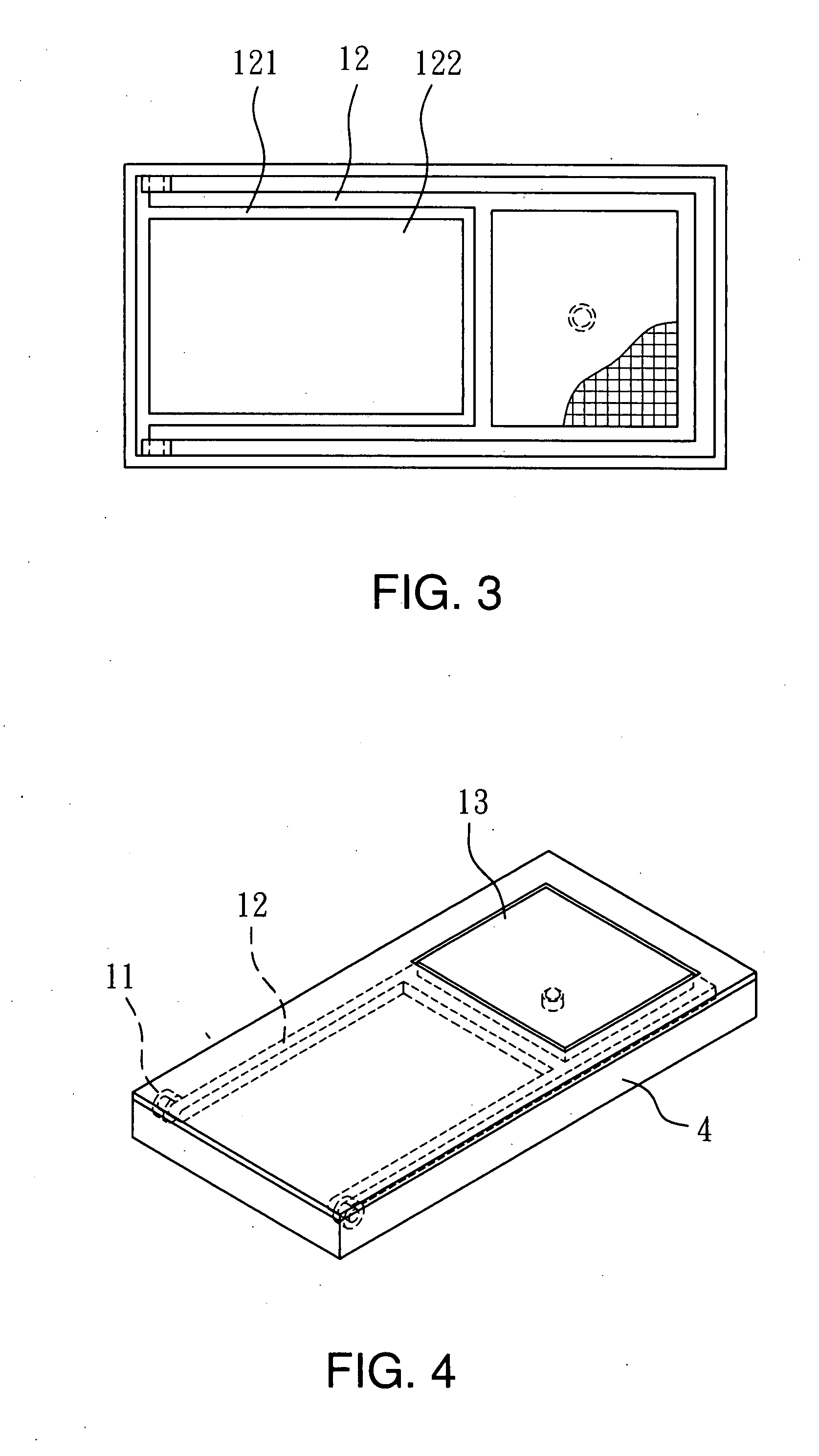
[0022]Refer to FIG. 3 for the invention. To meet the prevailing trend of slim and light for electronic products the extension zone 12 has a carved housing space 121 in the middle to hold other elements 122 such as a display device or circuit elements or the like.
third embodiment
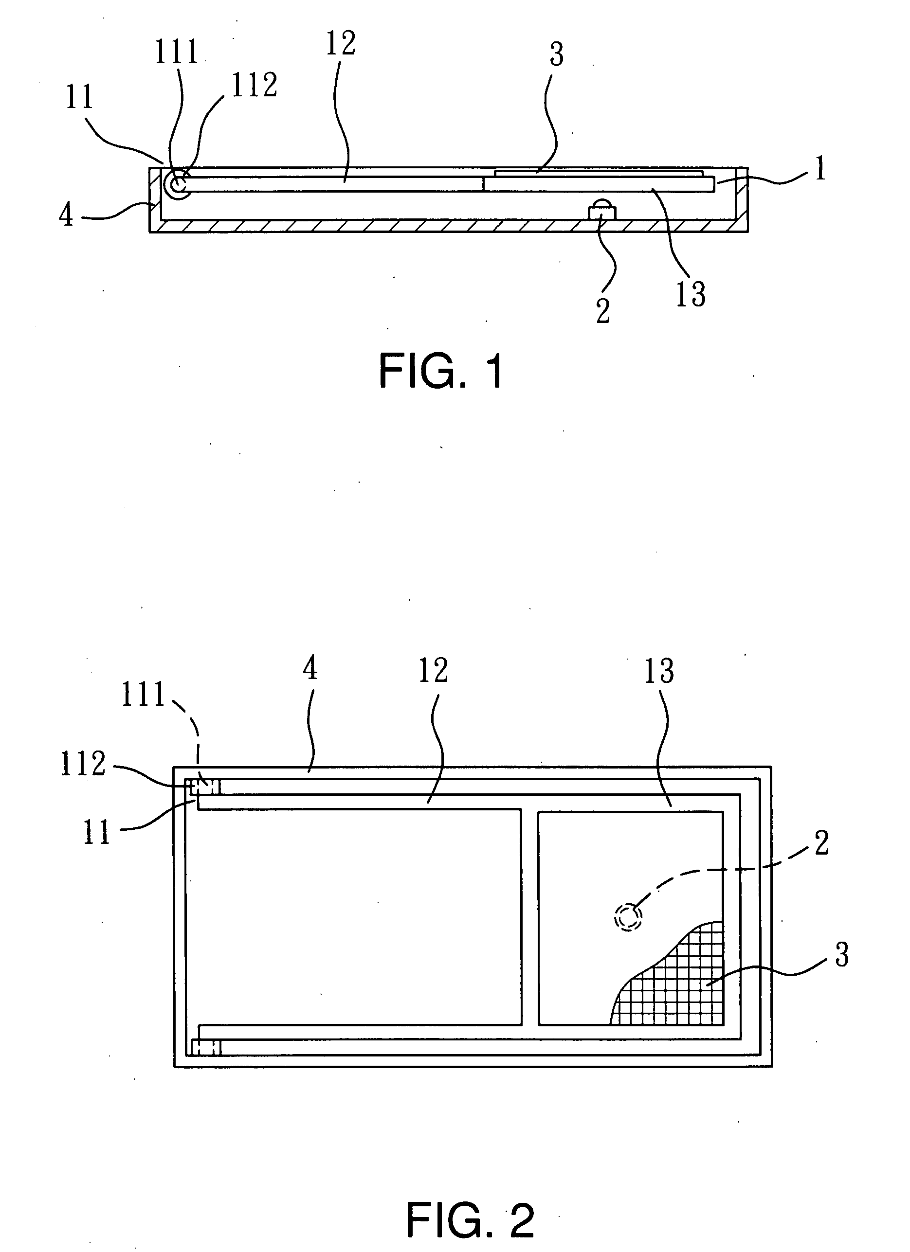
[0023]Refer to FIG. 4 for the invention. The invention can be integrated with (or replace) the input devices of the existing equipments. The extension zone 12 and axle mechanism 11 can be concealed in the interior of the chassis 4, and the click zone 13 is exposed outside the chassis 4 to enhance aesthetic appeal and safety.
fourth embodiment
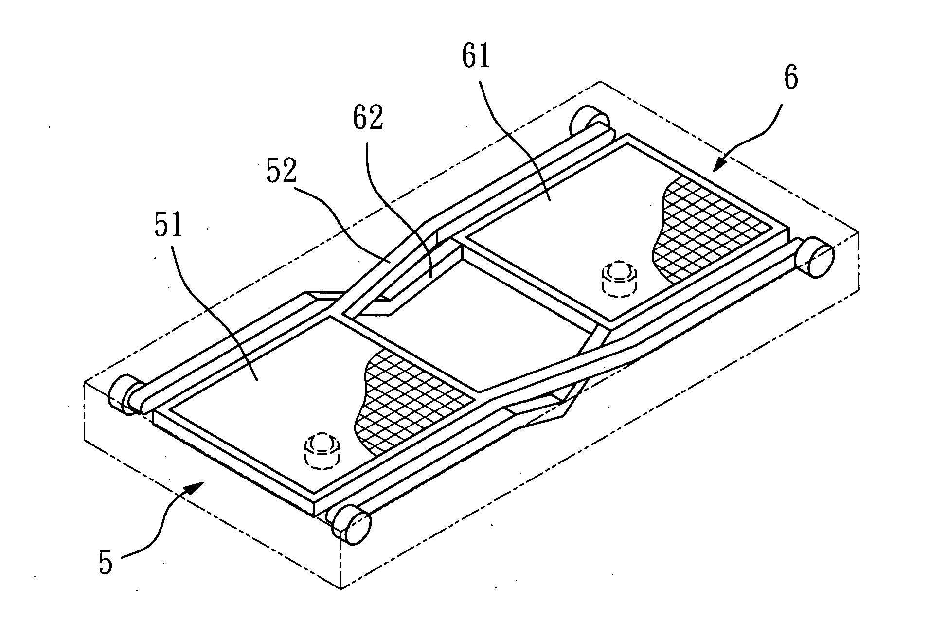
[0024]Refer to FIG. 5 for the invention. In a condition in which shrinking the size to provide more click zones 51 and 61 is desired, the invention may include two touch control click structures 5 and 6 installed in a cross manner. The structure is substantially same as the previous embodiments. The only difference is that two extension zones 52 and 62 are bent at the cross location to prevent them from jamming each other.
PUM
 Abstract
Description
Claims
Application Information