Image forming system and image forming apparatus

a technology of image forming system and forming apparatus, which is applied in the direction of electrographic process apparatus, instruments, optics, etc., can solve the problems of wasted waiting time, achieve the effect of preventing the reduction of image forming efficiency, reducing waiting time, and reducing image forming efficiency

Inactive Publication Date: 2010-10-07
KONICA MINOLTA BUSINESS TECH INC
View PDF4 Cites 4 Cited by
  • Summary
  • Abstract
  • Description
  • Claims
  • Application Information

AI Technical Summary

Benefits of technology

[0009]However, since the technique of Patent Document 1 sets a sheet feeding interval before and after switching of the ejection tray to a fixed value, the sheet feeding interval needs to be set to be the largest difference of necessary time for conveyance between a combination of ejection trays among a plurality of combinations. When an actual difference of necessary time for conveyance at the time when the ejection tray is changed is small, there is a possibility that wasted waiting time occurs. Although the technique of Patent Document 2 can wait resist processing depending on a transfer sheet size and the like, waiting time occurs similarly to the above so that image forming efficiency is reduced. For this reason, in order to prevent the image forming efficiency from reducing, when changing the ejection tray, combinations of finishers before and after the changing have to be restricted.
[0010]According to a first aspect of the present invention, there is disclosed an image forming system including: an image forming apparatus to form an image on a sheet conveyed from a feeding section to eject the sheet; and a plurality of finishers each including one or a plurality of ejection trays, which finishers are connected to the image forming apparatus and perform finishing to the sheet ejected from the image forming apparatus, wherein the image forming apparatus includes a control section to determine a sheet feeding interval of the feeding section based on a position of the ejection tray to which a first sheet is ejected and a position of the ejection tray to which a second sheet is ejected, an image-forming order of the second sheet being immediately before an image-forming order of the first sheet.
[0011]According to a first aspect of the present invention, there is disclosed an image forming apparatus which is connected to a plurality of finishers each including one or a plurality of ejection trays so as to enable a data transmission and reception, and which apparatus forms an image on a sheet conveyed from a feeding section to eject the sheet, the image forming apparatus including: a control section to determine a sheet feeding interval of the feeding section based on a position of the ejection tray to which a first sheet is ejected and a position of the ejection tray to which a second sheet is ejected, an image-forming order of the second sheet being immediately before an image-forming order of the first sheet.

Problems solved by technology

As a result, when printing restarts after jam processing, an image forming operation re-performs printing of the sheet 1 and does not re-perform printing of the sheet 2.
When an actual difference of necessary time for conveyance at the time when the ejection tray is changed is small, there is a possibility that wasted waiting time occurs.

Method used


Image

  • Image forming system and image forming apparatus
  • Image forming system and image forming apparatus
  • Image forming system and image forming apparatus

Examples


first embodiment

[0021]Although embodiments of the present invention will be described below with reference to the drawings, the present invention is not limited to the following embodiments. The embodiments are intended to show the best modes for implementing the present invention and are not intended to limit the scope of the present invention.

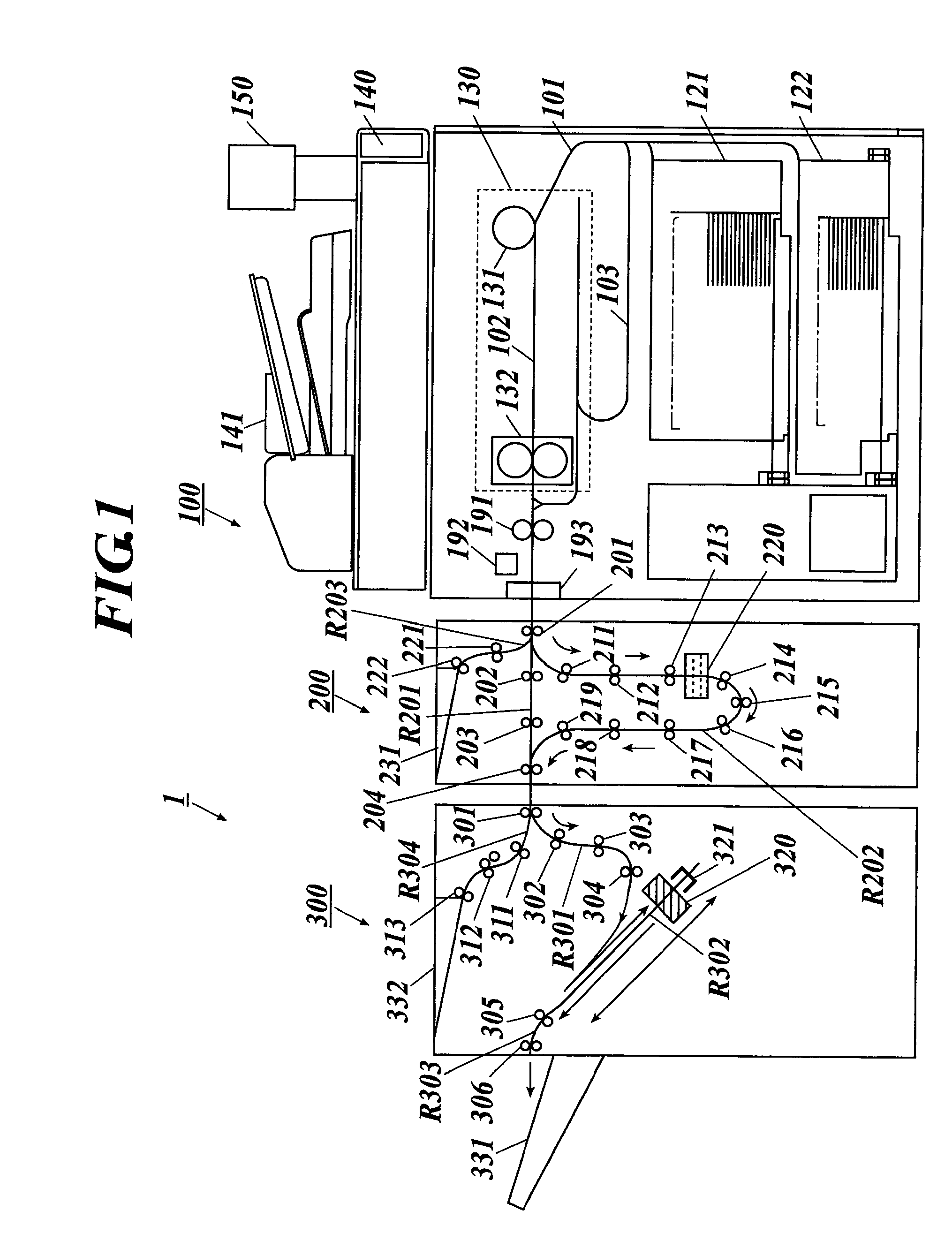
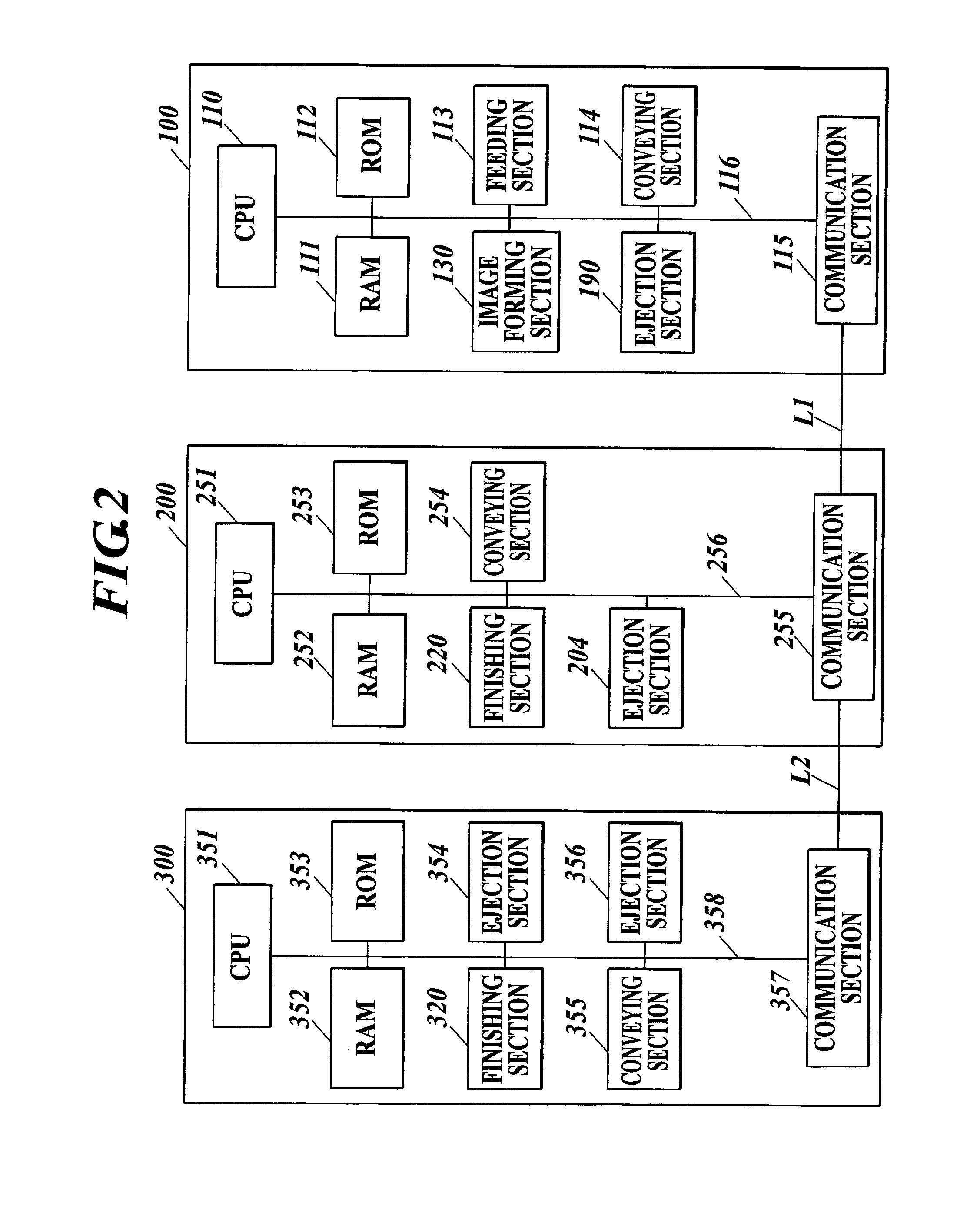
[0022]A configuration of an image forming system according to the embodiment will be firstly described. As shown in FIG. 1, the image forming system 1 includes an image forming apparatus 100, a first finisher 200 and a second finisher 300.

[0023]The image forming apparatus 100 includes storage sections 121, 122, an image forming section 130, and image reading section 140, an auto document conveying section 141, a display / operation section 150, a sheet ejection roller 191, a sheet ejection sensor 192, a sheet ejection exit 193, and so on. The image forming apparatus 100 further includes a conveying path 101 for feeding sheets from the storage sections 121, 122...

second embodiment

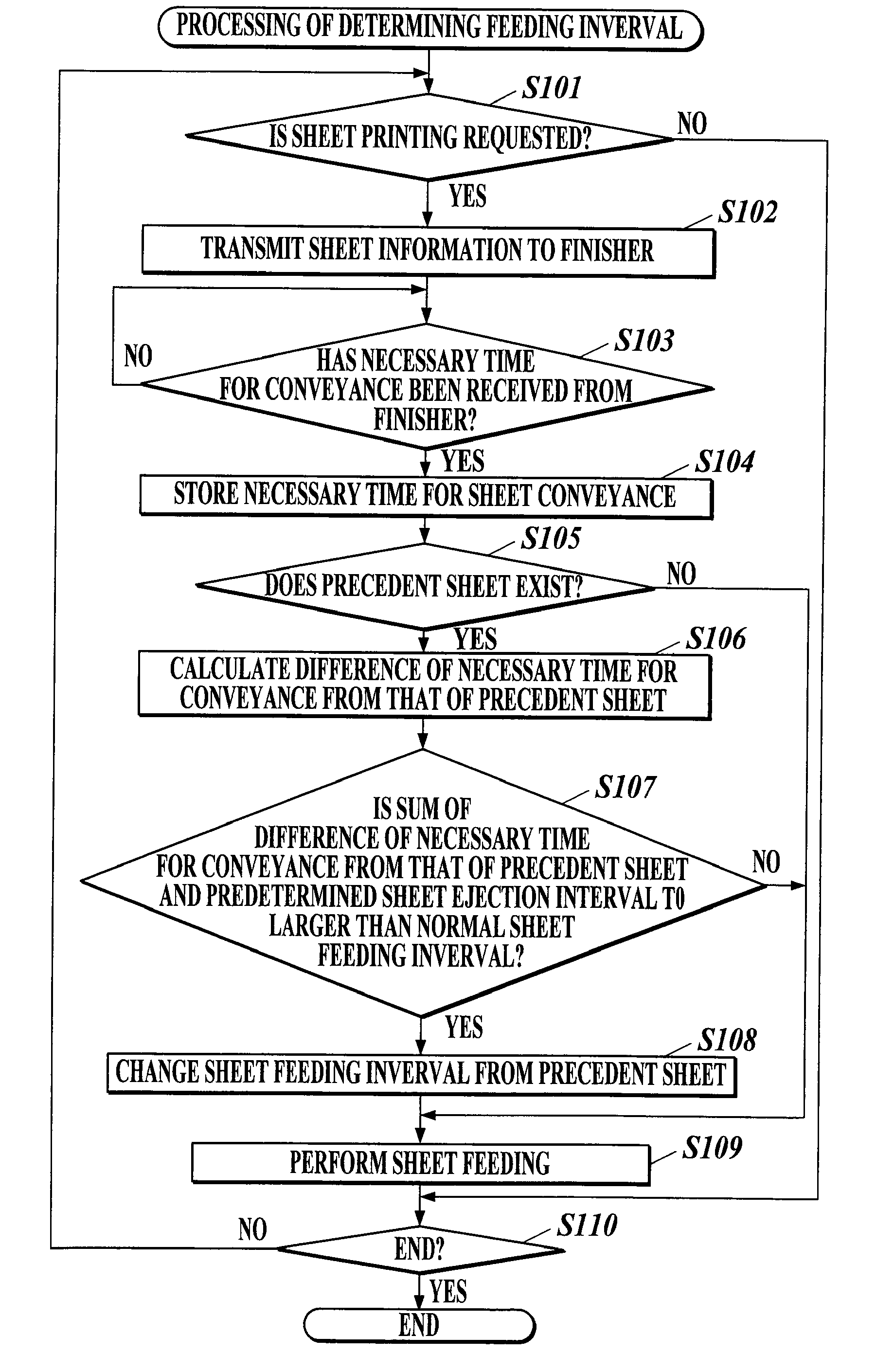
[0097]Next, the second embodiment of the image forming system 1 according to the present invention will be described. The second embodiment is different from the first embodiment in the point that the necessary time for conveyance is calculated in the image forming apparatus 100. Hereinafter, the processing of determining the feeding interval (referred to as processing B of determining the feed interval in order to distinguish from the first embodiment) for determining the sheet feeding interval and the processing of calculating the necessary time for conveyance will be described.

[0098]FIG. 7 shows a flowchart of the processing B of determining the feeding interval to be performed in the image forming apparatus 100. The processing B of determining the feeding interval is performed by the CPU 110 in cooperation with the program stored in the ROM 111.

[0099]Firstly, it is judged whether or not the sheet print request is input (Step S301). When it is not judged that the print request is...


PUM


Abstract

Disclosed an image forming system including: an image forming apparatus to form an image on a sheet conveyed from a feeding section to eject the sheet; and a plurality of finishers each including one or a plurality of ejection trays, which finishers are connected to the image forming apparatus and perform finishing to the sheet ejected from the image forming apparatus, wherein the image forming apparatus includes a control section to determine a sheet feeding interval of the feeding section based on a position of the ejection tray to which a first sheet is ejected and a position of the ejection tray to which a second sheet is ejected, an image-forming order of the second sheet being immediately before an image-forming order of the first sheet.

Description

BACKGROUND[0001]1. Field of the Invention[0002]The present invention relates to an image forming system and an image forming apparatus.[0003]2. Description of Related Art[0004]In recent years, there has been a print-on-demand (POD) system which is provided with a plurality of finishers connected to a main body of an image forming apparatus and receives a plurality of printing reservations for sheets whose sheet ejection conditions such as finishing and an ejection tray to which a sheet is ejected are different from one another to enable executing continuous printing. A sheet conveying path and an ejection tray have been generally different for each kind of finishing. Even in the case of the same finishing, a way of using a different ejection tray for each sheet has been adopted.[0005]In this case, when there are two sheets for which both of conveying paths and ejection trays are different from each other, and for example when printing of sheet 1 for which necessary time from feeding...

Claims


Application Information

Patent Timeline
Patent Type & Authority Applications(United States)
IPC IPC(8): G03G15/00
CPCG03G15/6505G03G15/6552G03G15/6558G03G2215/00949G03G2215/00599G03G2215/00734G03G2215/00556
Inventor SAITSU, YASUSHI
Owner KONICA MINOLTA BUSINESS TECH INC
Why Eureka
Try Eureka