Method and Apparatus for Reducing Head Media Spacing in a Disk Drive

a disk drive and media spacing technology, applied in the direction of maintaining the head carrier alignment, recording information storage, instruments, etc., can solve the problem of not preventing the actuated portion of the air bearing surface, and achieve the effect of reducing modulation, reducing interfacial forces, and reducing corrosion and wear protection

Inactive Publication Date: 2010-10-21
FIRST PRINCIPALS +1
View PDF29 Cites 29 Cited by
  • Summary
  • Abstract
  • Description
  • Claims
  • Application Information

AI Technical Summary

Benefits of technology

[0043]The typical read-write sensors have a cross-section of about 0.1 microns by about 0.1 microns (0.01 microns2). Even in embodiments where the protruding feature has a cross section of about 1 micron2, the protruding feature still has a cross-sectional area 100 times larger than the read-write sensors. Consequently, the protruding feature provides adequate corrosion and wear protection, while still being small enough to penetrate the lubricant layer without generating unacceptable vibration.
[0044]In some embodiments, the protruding feature can be shaped to further reduce modulation due to interaction with the lubricant. For example, the protruding feature can have a rectangular cross-section, rather than square. In one embodiment, the narrower side of a rectangular protruding feature acts as a leading edge cutting through the lubricant. The shape of the protruding feature can be rectangular, elliptical, triangular, teardrop, or a random shape to further lower the interfacial forces with the lubricant and optimize the clearance of the heat activated shape. The shape of the protruding feature can also be designed to match the shape of the protruded trailing edge area due to heating. The most likely scenario is an elliptical shape.

Problems solved by technology

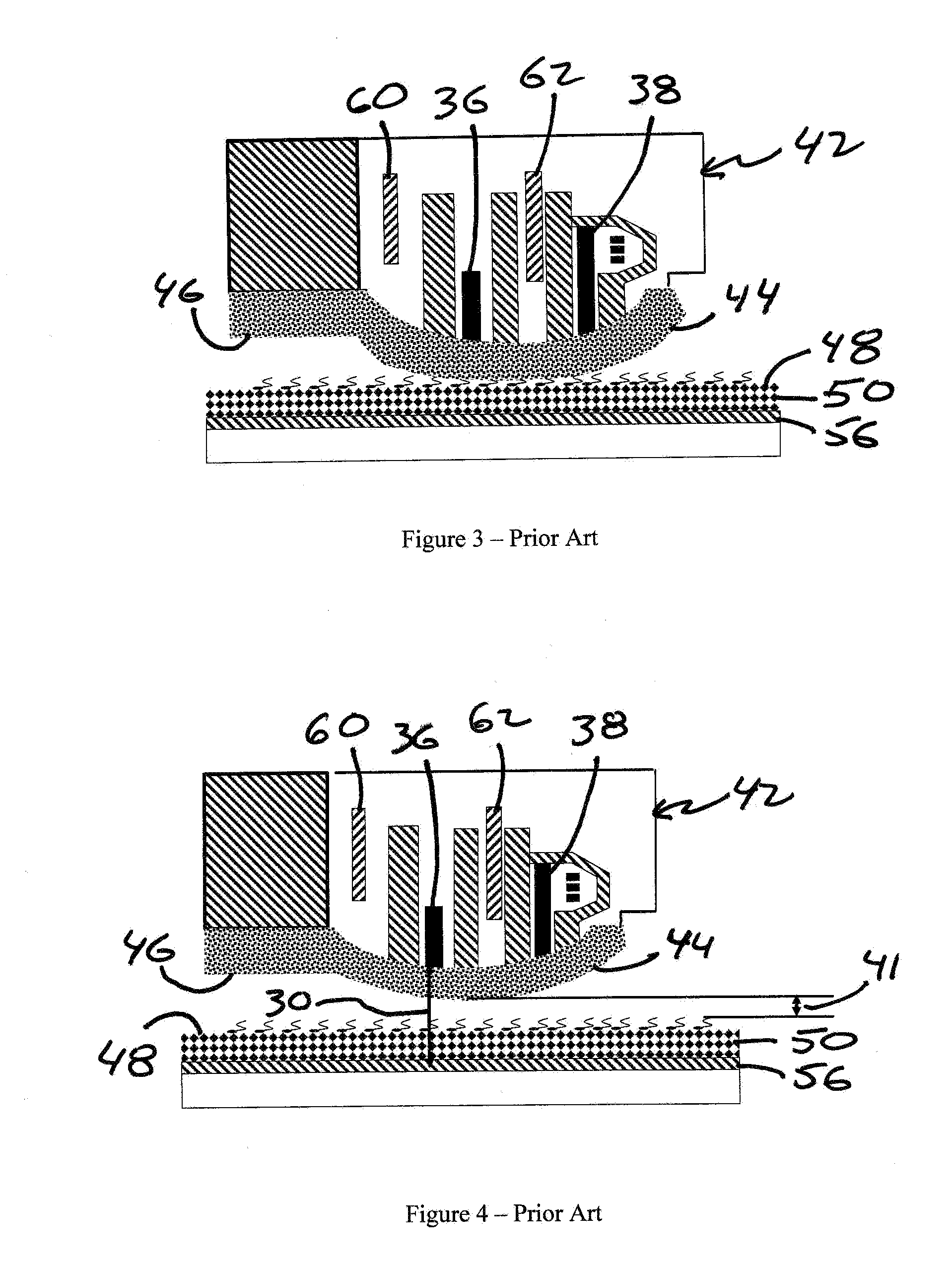
Consequently, the protruding feature does not prevent the actuated portion of the air bearing surface from interacting with the lubricant layer.

Method used


Image

  • Method and Apparatus for Reducing Head Media Spacing in a Disk Drive
  • Method and Apparatus for Reducing Head Media Spacing in a Disk Drive
  • Method and Apparatus for Reducing Head Media Spacing in a Disk Drive

Examples


Embodiment Construction

[0101]The systems and methods disclosed herein reduces the current HMS of about 100 Angstroms to about 65 Angstroms or less, without substantial carbon overcoat reductions or lubricant reduction. This reduction in HMS will enable the industry to achieve 1 Tbit / in2 with minor engineering design changes to the current air bearing and heater implementations.

[0102]While the prior art typically relied on the indiscriminate application of carbon overcoat to protect both sensitive and non-critical area, the embodiments disclosed herein selectively retain carbon overcoat in critical areas to protect the transducer areas against corrosion and wear.

[0103]FIGS. 9A and 9B illustrate an alternate read-write head 100 in accordance with an embodiment of the present invention. Thickness of the carbon overcoat 102 is reduced across the air bearing surface 104, except for protruding feature 106 protecting read-write sensors 110, 112. Since the requirement of wear durability is more stringent than cor...


PUM

PropertyMeasurementUnit
heightaaaaaaaaaa
areaaaaaaaaaaa
areaaaaaaaaaaa

Abstract

Systems and methods for reducing head media spacing (HMS) from about 100 Angstroms to about 65 Angstroms or less, without substantial reductions in the carbon overcoat or lubricant thickness. A protruding feature extends above the actuated portion of the air bearing surface and generally covers the read-write sensors. The protruding feature can either be static or thermally actuated. The protruding feature is small enough to engage with the lubricant without causing large head media disturbances and lubricant pickup and re-distribution or preventing contact detection. The protruding feature is also extremely small relative to the size of the actuated portion of the air bearing surface, but large enough to provide a wear and corrosion resistance to head media spacing sensitive features.

Description

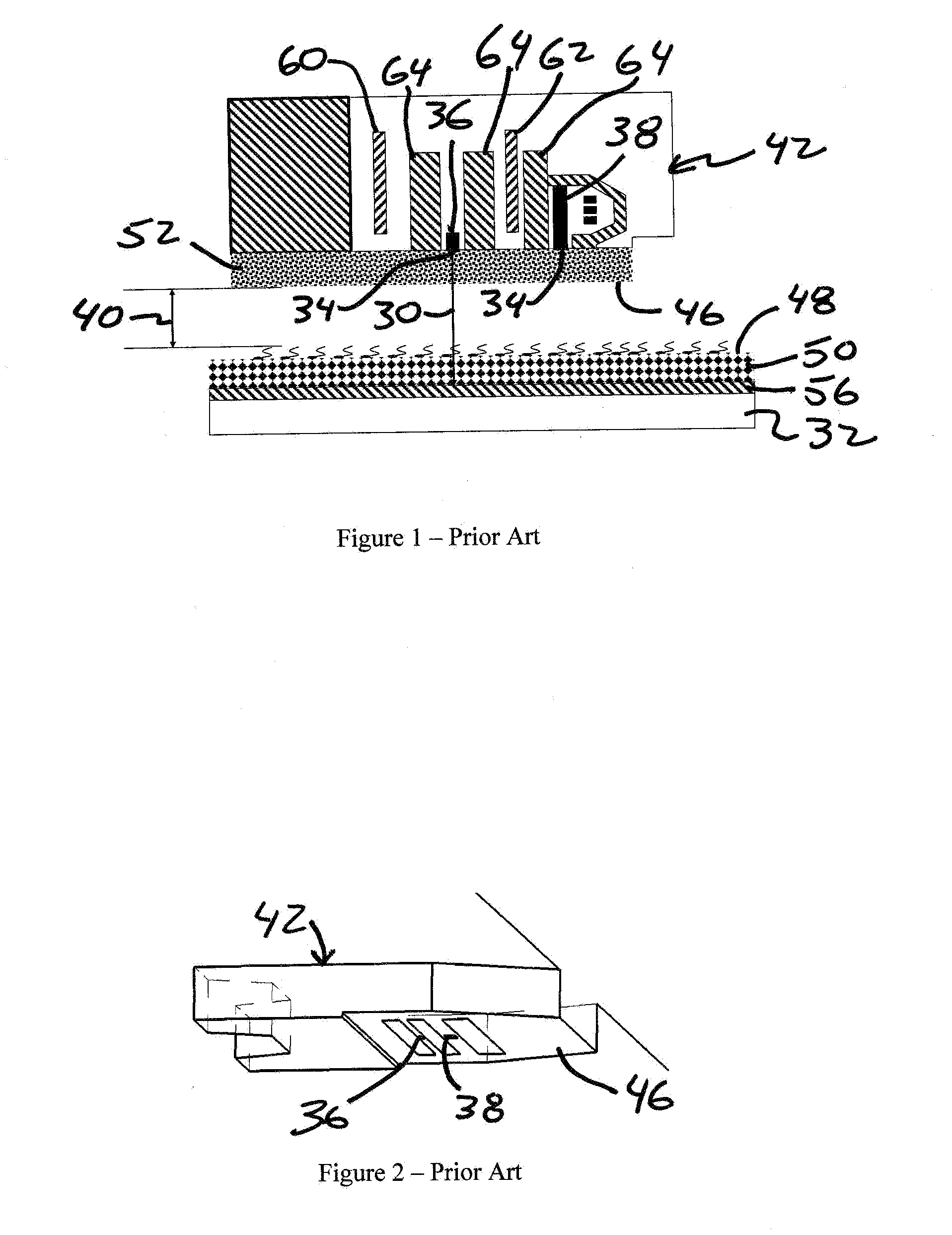
FIELD OF THE INVENTION[0001]The present application is directed to a read-write head for a disk drive with a protruding feature on the air bearing surface adapted to penetrate into the lubricant while reliably performing read-write operations, thereby reducing head-media spacing (HMS).BACKGROUND OF THE INVENTION[0002]The realization of a data density of 1 Terabyte / inch2 (1 Tbit / in2) depends, in part, on designing a head-disk interface (HDI) with the smallest possible head-media spacing HMS. As used herein, “head-media spacing” or “HMS” refer to the distance between a read or write sensor and a surface of a magnetic media.[0003]As illustrated in FIG. 1 the HMS 30 is the distance from magnetic media 32 to distal ends 34 of read-write sensors 36, 38. Shielding 64 is also commonly located near the read-write sensors 36, 38. Head-media spacing 30 is the sum of the clearance 40 and the spacing losses contributed by both the head 42 and the media 32. The passive clearance 40 provides a rel...

Claims


Application Information

Patent Timeline
Patent Type & Authority Applications(United States)
IPC IPC(8): G11B5/60
CPCG11B5/6005G11B5/3106G11B5/6064
Inventor BOUTAGHOU, ZINE-EDDINESCHWAPPACH, KARL
Owner FIRST PRINCIPALS
Why Eureka
Try Eureka