Medicine Cabinet

Active Publication Date: 2010-10-28
ROBERN INC
View PDF33 Cites 16 Cited by
  • Summary
  • Abstract
  • Description
  • Claims
  • Application Information

AI Technical Summary

Benefits of technology

[0016]Note also that when the accessories like a shaver are not in use, they can be stored on shelving of the cabinet with their

Problems solved by technology

Regardless, the structures used to house the needed electrical wiring for electrified medicine cabinets were not optimal.
For example, when a pivoting front door was provided, and the door was open, the mirror on the front of the door was no longer easily usable.
This is not only somewhat ugly, it exposes the outlet to an environme

Method used


Image

  • Medicine Cabinet
  • Medicine Cabinet
  • Medicine Cabinet

Examples


Embodiment Construction

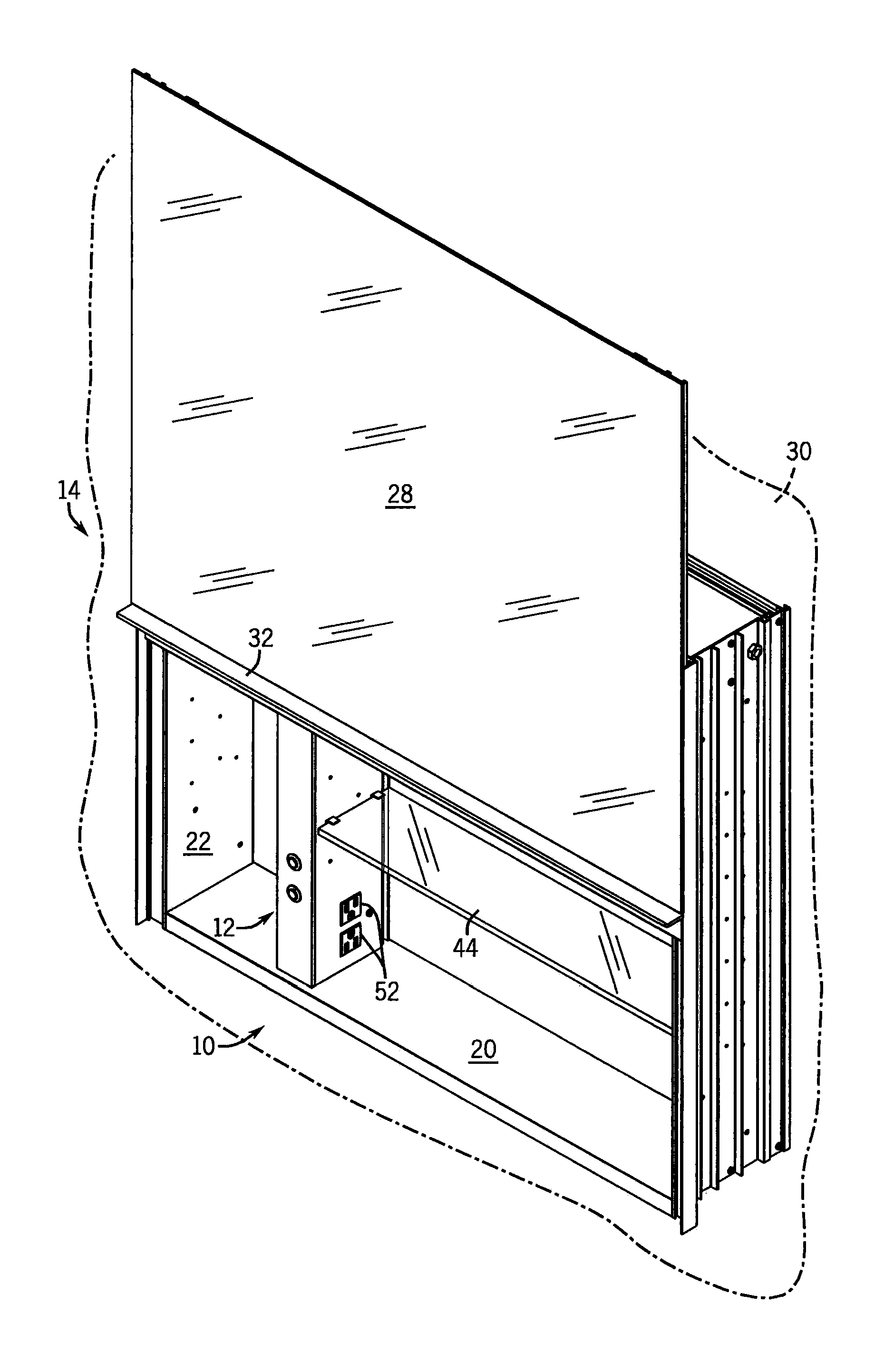
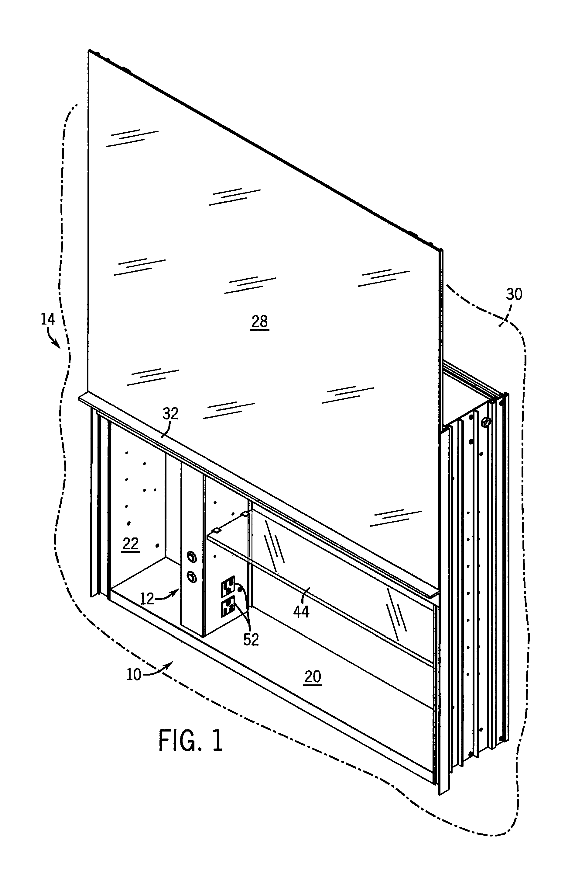
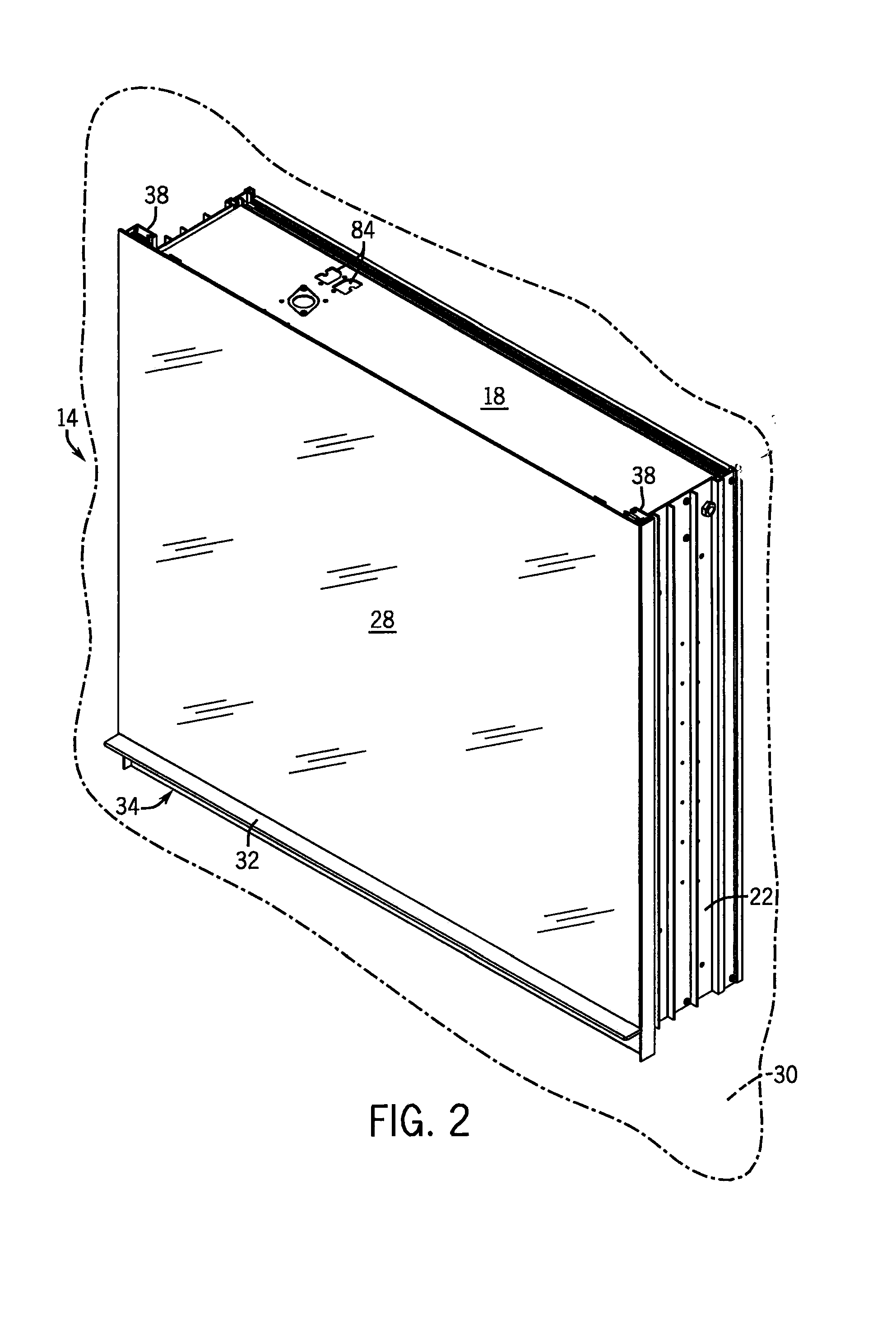
[0028]A preferred assembly, generally 10, is shown in the drawings. There is shown a medicine cabinet 14 having a top wall 18, a bottom wall 20, opposed side walls 22, and preferably a rear wall 24, which together define an internal cavity. Dividing the cavity is a wire management raceway generally 12. There is also a front door 28 (preferably mirrored and vertically slidable). For example the door 28 can have a horizontally extending handle 32 fixed along a lower edge 34 thereof to facilitate lifting and lowering of the door 28. There can also be a counterweight 36 (equal to the weight of the door 28).

[0029]The door 28 is slidably retained within a set of vertical tracks 38 formed along the side walls 22 of the enclosure 16. The door 28 is connected to the counterweight 36 via a pair of toothed belts 40 extending over a roller 41 and respective gear wheels 42. The belts 40 engage and cooperate with the wheels 42 when lifting or lowering the door 28. Door 28 may be maintained in a p...


PUM


Abstract

A medicine cabinet is disclosed that has electrical power. An internal raceway is provided to hide the electrical wiring for the cabinet, accommodate power cords of appliances powered by the cabinet, and to support shelving. A vertically movable front mirrored door can be raised to access the power supply and/or cabinet storage space.

Description

CROSS-REFERENCES TO RELATED APPLICATIONS[0001]Not Applicable.STATEMENT REGARDING FEDERALLY SPONSORED RESEARCH[0002]Not Applicable.BACKGROUND OF THE INVENTION[0003]The present invention relates to storage cabinets such as medicine cabinets. More particularly it relates to improvements in positioning and storing electrical wiring for these cabinets, and power cords for appliances and other items stored in the cabinet.[0004]It is conventional to provide wall-hung “medicine” cabinets in homes that are used to store cosmetics, drugs, and other personal items. Some of these cabinets are provided with electrical power (e.g. to light the cabinet itself and / or to provide a plug-in site for personal care devices such as hair dryers, curling irons, toothbrushes and shavers). See generally U.S. Pat. No. 5,355,627.[0005]Most such cabinets have their front door pivot open on a vertical hinge. However, some provide a front door that slides vertically. See e.g. U.S. Pat. No. 2,331,655.[0006]Regardl...

Claims


Application Information

Patent Timeline
IPC IPC(8): A47B81/00F16L3/08
CPCA47B67/02
Inventor PANDORF, ROBERT P.DIEMEL, DOUGLAS J.KATZ, HOWARD S.
Owner ROBERN INC
Why Eureka
Try Eureka