Logical map table for detecting dependency conditions

Active Publication Date: 2010-10-28
ORACLE INT CORP
View PDF32 Cites 23 Cited by
  • Summary
  • Abstract
  • Description
  • Claims
  • Application Information

AI Technical Summary

Benefits of technology

[0006]Techniques and structures are described herein allowing the detection of certain dependency conditions that may arise in association with the execution of two or more computer instructions, including the detection of evil twin conditions.
[0007]One way in which dependencies may be detected occurs in conjunction with a register renaming (or mapping) process. As instructions are being executed, destinations specified by one or more of the instructions may be mapped to a set of physical registers available for renaming. A logical map table (LMT) or other suitable structure may maintain information indicative of mappings. In some embodiments, a LMT may comprise a content-addressable memory (CAM).
[0008]One type of execution dependency that may arise during instruction execution involves, for example, two instructions, the first (initial one) of which specifies as a destination one portion of a register comprising at least two portions. The second (subsequent) instruction collectively specifies as a source two or more portions of the register. In some embodiments involving single-precision writes followed by a double-precision read, the situation described above can be referred to as an evil twin dependency.

Problems solved by technology

Such dependency conditions may result in an undesirable increase in execution time.
One type of dependency condition is a so-called “evil twin” condition, which can produce undesirable delays in execution, particularly in code that includes a large number of floating-point operations.

Method used


Image

  • Logical map table for detecting dependency conditions
  • Logical map table for detecting dependency conditions
  • Logical map table for detecting dependency conditions

Examples


Embodiment Construction

[0029]Co-pending U.S. patent application Ser. No. ______, entitled “Physically-Indexed Logical Map Table,” U.S. patent application Ser. No. ______, entitled “Apparatus and Method for Handling Dependency Conditions,” and U.S. patent application Ser. No. ______, entitled “Processor Operating Mode For Mitigating Dependency Conditions,” are filed concurrently with the present application and are incorporated by reference herein in their entireties.

[0030]This specification includes references to “one embodiment” or “an embodiment.” The appearances of the phrases “in one embodiment” or “in an embodiment” do not necessarily refer to the same embodiment. Particular features, structures, or characteristics may be combined in any suitable manner consistent with this disclosure.

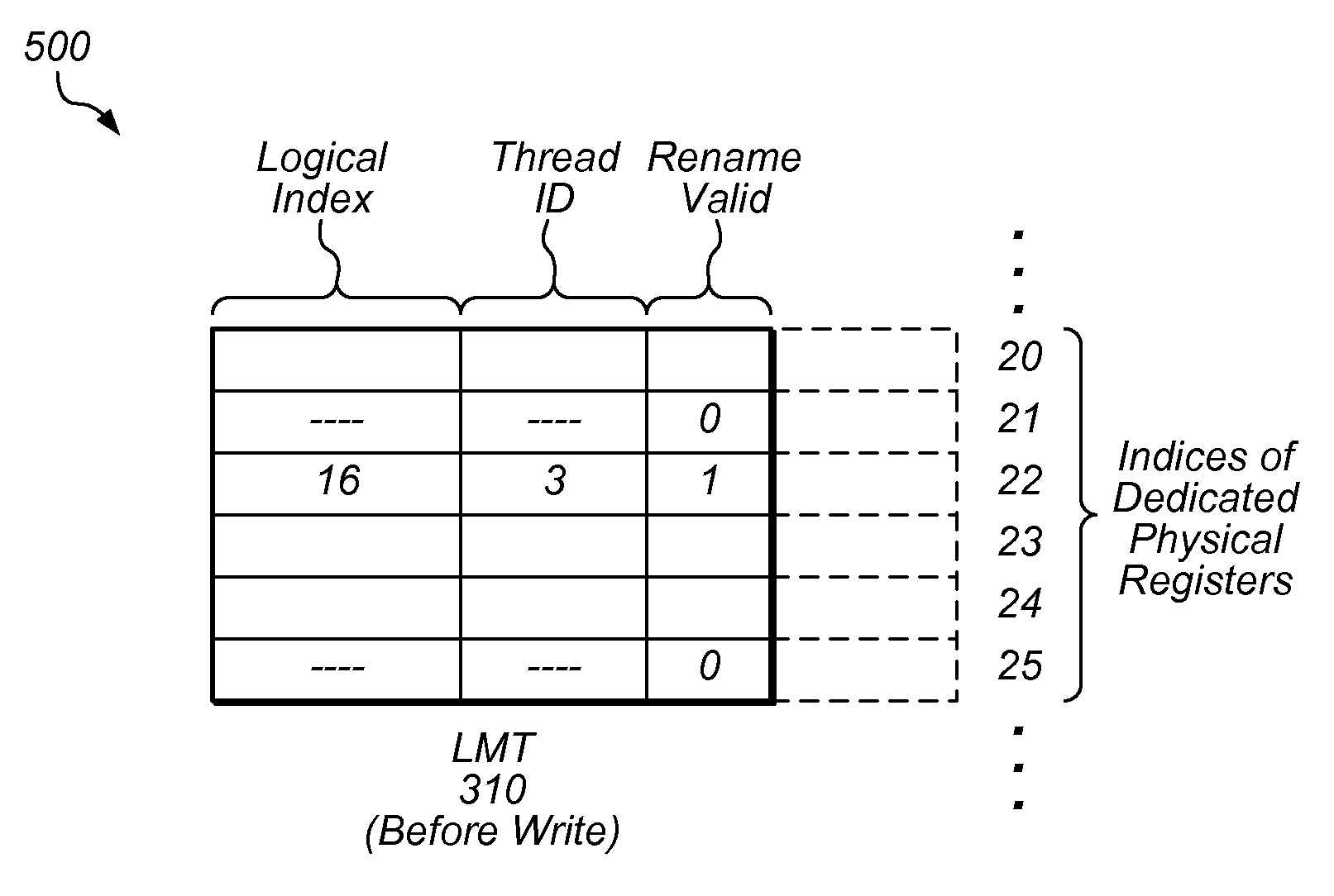
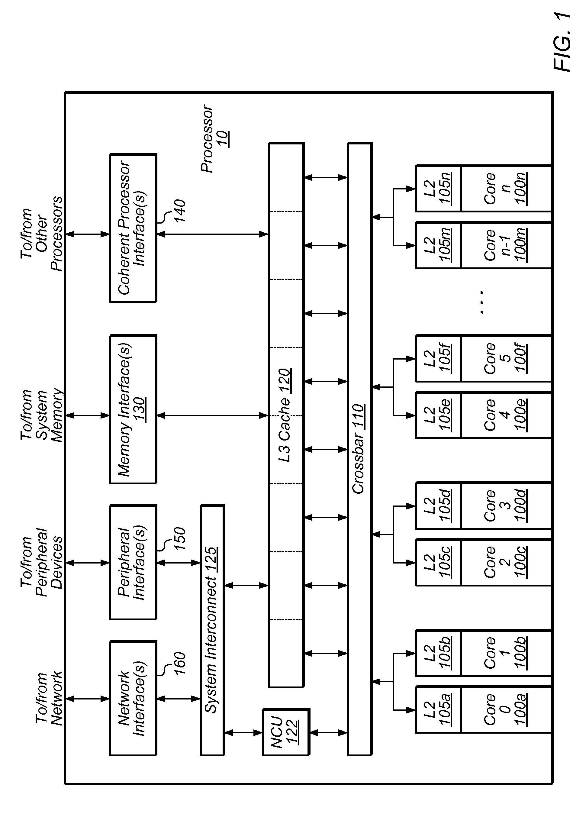
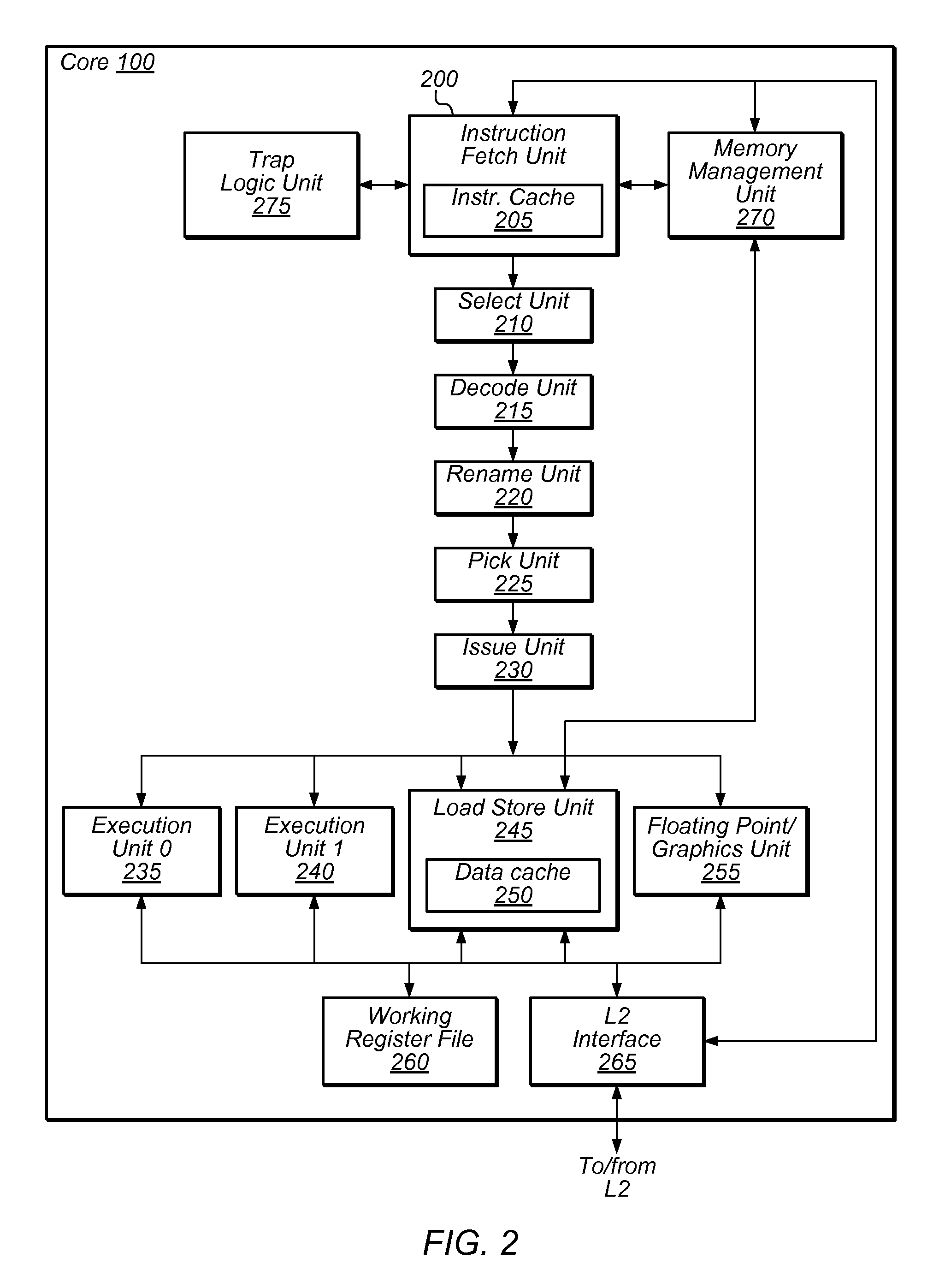
[0031]FIGS. 1-2 present an overview of an exemplary processor. FIGS. 3-8 relate to embodiments of a physically indexed logical map table. FIGS. 9A-D describe dependency conditions, one instance of which may be referred ...


PUM


Abstract

Techniques and structures are described which allow the detection of certain dependency conditions, including evil twin conditions, during the execution of computer instructions. Information used to detect dependencies may be stored in a logical map table, which may include a content-addressable memory. The logical map table may maintain a logical register to physical register mapping, including entries dedicated to physical registers available as rename registers. In one embodiment, each entry in the logical map table includes a first value usable to indicate whether only a portion of the physical register is valid and whether the physical register includes the most recent update to the logical register being renamed. Use of this first value may allow precise detection of dependency conditions, including evil twin conditions, upon an instruction reading from at least two portions of a logical register having an entry in the logical map table whose first value is set.

Description

BACKGROUND OF THE INVENTION[0001]1. Field of the Invention[0002]This disclosure relates generally to computer processors, and particularly to detecting dependency conditions within computer processors.[0003]2. Description of the Related Art[0004]Computer processors are capable of executing various instructions. During the execution of instructions, a dependency condition may exist between a first and a second, subsequent instruction such that executing the second computer instruction requires a value resulting from the first instruction's execution. Such dependency conditions may result in an undesirable increase in execution time.[0005]One type of dependency condition is a so-called “evil twin” condition, which can produce undesirable delays in execution, particularly in code that includes a large number of floating-point operations.SUMMARY[0006]Techniques and structures are described herein allowing the detection of certain dependency conditions that may arise in association with ...

Claims


Application Information

Patent Timeline
IPC IPC(8): G06F9/30
CPCG06F9/384G06F9/30109
Inventor GOLLA, ROBERT T.BARREH, JAMA I.BROOKS, JEFFREY S.LEVY, HOWARD L.
Owner ORACLE INT CORP
Why Eureka
Try Eureka