Method and system for control of desiccant dehumidifier

a technology of desiccant dehumidifier and control method, which is applied in the field of process drying system and method, heat transfer system and method, and ventilation system and method, can solve the problem of needing to control the capacity of the dehumidification system, and achieve the effect of reducing the amount of heat transfer

Active Publication Date: 2010-11-04
BRY AIR +1
View PDF30 Cites 74 Cited by
  • Summary
  • Abstract
  • Description
  • Claims
  • Application Information

AI Technical Summary

Benefits of technology

[0081]In another embodiment, a speed regulation mechanism is provided to vary the rotational speed of the desiccant wheel to control the amount of moisture removed from the supply air stream and / or minimize the amount of heat transferred to the supply air stream.

Problems solved by technology

Such instantaneous changes of moisture, and resultant moisture load, require the need to control the capacity of the dehumidification system.

Method used


Image

  • Method and system for control of desiccant dehumidifier
  • Method and system for control of desiccant dehumidifier
  • Method and system for control of desiccant dehumidifier

Examples


Embodiment Construction

[0113]The present invention will now be described with reference to accompanying drawings which are illustrative of certain embodiments of the invention. Variations and modifications are possible without departing from the spirit and scope of the invention.

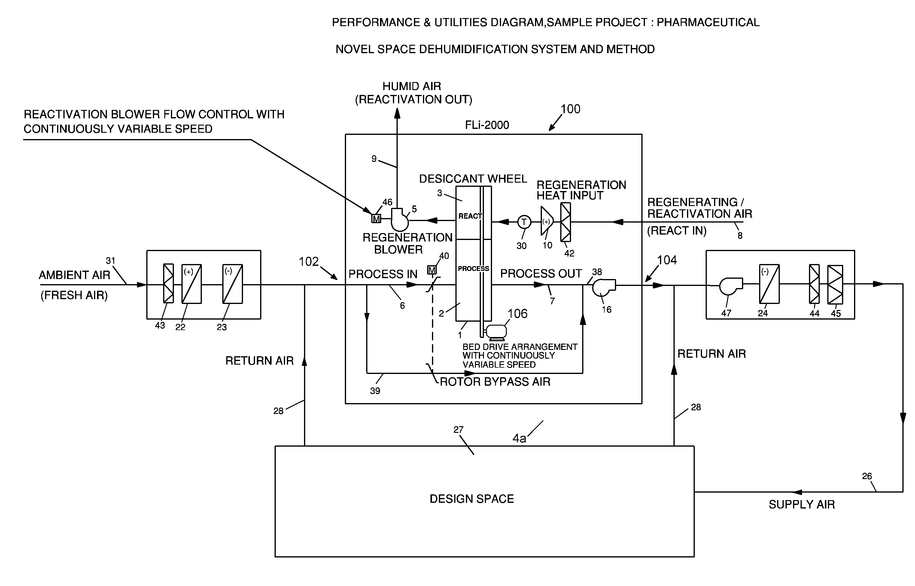
[0114]FIG. 9(a) is a schematic illustrating an embodiment of a space dehumidification system. There is an internal bypass 39 interlinked with the process airflow 6 through a face and bypass damper 40. Based on the humidity measured in the design space 27, and with instantaneous and changing loads, the face and bypass damper 40 modulates the amount of airflow passing through the wheel, while bypassing the rest of the airflow. As and when there is a need to supply fresh air 31 for the space design need, it is generally introduced at the inlet of the dehumidifier, and combined with the returning air 28 from the design space 27. Depending on the application, it may be advantageous to heat or cool the fresh air 31 before it mixes with ...


PUM

PropertyMeasurementUnit
RHaaaaaaaaaa
RHaaaaaaaaaa
rotational speedaaaaaaaaaa

Abstract

An active wheel desiccant dehumidifier is controlled for improved energy savings by modulating operation characteristics including process air flow, reactivation air flow, temperatures, and wheel rotation in response to changing conditions.

Description

RELATED APPLICATION[0001]The present application claims the benefit of U.S. Ser. No. 61 / 175,119 filed May 4, 2009, the disclosure of which is hereby incorporated herein by reference in its entirety. This application is also related to a PCT application filed in India, and an Indian National application, for both of which the disclosure is hereby incorporated herein by reference in its entirety, both filed on or before May 3, 2010. First named inventor in both applications is Deepak Pahwa. This application is also related to Mexican national application and a Canadian national application both planned to be filed on or about May 4, 2010 with first named inventor William C. Griffiths, same as the first named inventor in the present application. The PCT Application, Indian National Application, Mexican National Application, Canadian National Application, and present application all have the same three inventors.FIELD OF THE INVENTION[0002]The present invention relates generally to heat...

Claims


Application Information

Patent Timeline
Patent Type & Authority Applications(United States)
IPC IPC(8): B01D53/06B01D53/02
CPCB01D53/0454B01D53/06B01D53/261B01D2253/104F24F2203/1088B01D2253/108B01D2259/4009B01D2259/4508F24F3/1423B01D2253/106
Inventor GRIFFITHS, WILLIAM C.PAHWA, DEEPAKSACHDEV, RAJAN
Owner BRY AIR
Why Eureka
Try Eureka