Mounting systems for solar panels

a solar panel and mounting system technology, applied in solar thermal energy generation, candle holders, lighting support devices, etc., can solve problems such as different challenges that need to be addressed in systems

Inactive Publication Date: 2010-11-04
APPLIED ENERGY TECH
View PDF28 Cites 258 Cited by
  • Summary
  • Abstract
  • Description
  • Claims
  • Application Information

AI Technical Summary

Benefits of technology

[0005]Also disclosed herein are embodiments of ground and roof mounting systems for at least one solar panel with various embodiments of panel and rail connectors. One embodiment of a mounting system for at least one solar panel comprises one or more of a connecting system to connect two beams without the need of a drill comprising a first slot configured to receive a lower beam and a second slot substantially perpendicular to the first slot and configured to receive an upper beam; a connecting system to connect two tubes without the need of a drill comprising a horizontal tube, a vertical tube integral with the horizontal tube, wings extending from at least the vertical tube on opposite sides

Problems solved by technology

The different mounting systems pose diffe

Method used


Image

  • Mounting systems for solar panels
  • Mounting systems for solar panels
  • Mounting systems for solar panels

Examples


Embodiment Construction

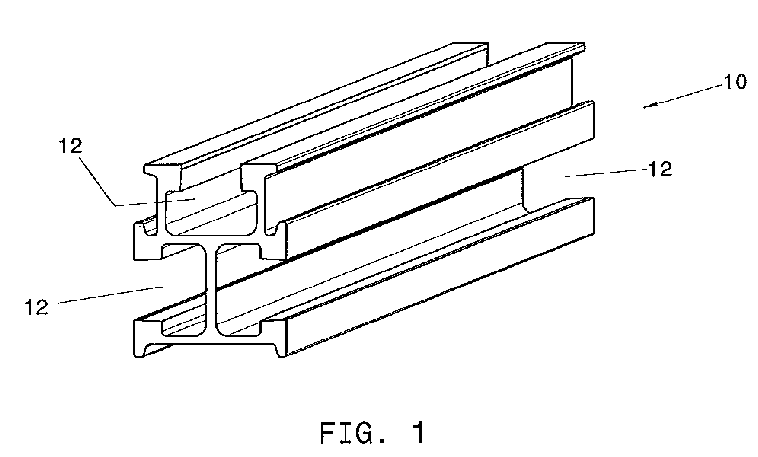
[0038]FIG. 1 illustrates a rail 10 that can be used with the mounting systems disclosed herein. The rail 10 is exemplary and other rail configurations can be used with any of the mounting systems herein. The rail 10 has three channels 12 of equal dimensions. The symmetrical channels on three sides of the rail 10 make the rail versatile, allowing for many different attachments extending from the rail 10 in three different directions. With the symmetrical channels 12, the rail 10 can be positioned as desired to attachment in the three directions of choice. The rails can be made of aluminum to resist corrosion and lengthen the operational life of the system. However, other appropriate materials can be used as desired or required by those skilled in the art. Another non-limiting example of rails that can be used with the systems disclosed herein include I beam rails.

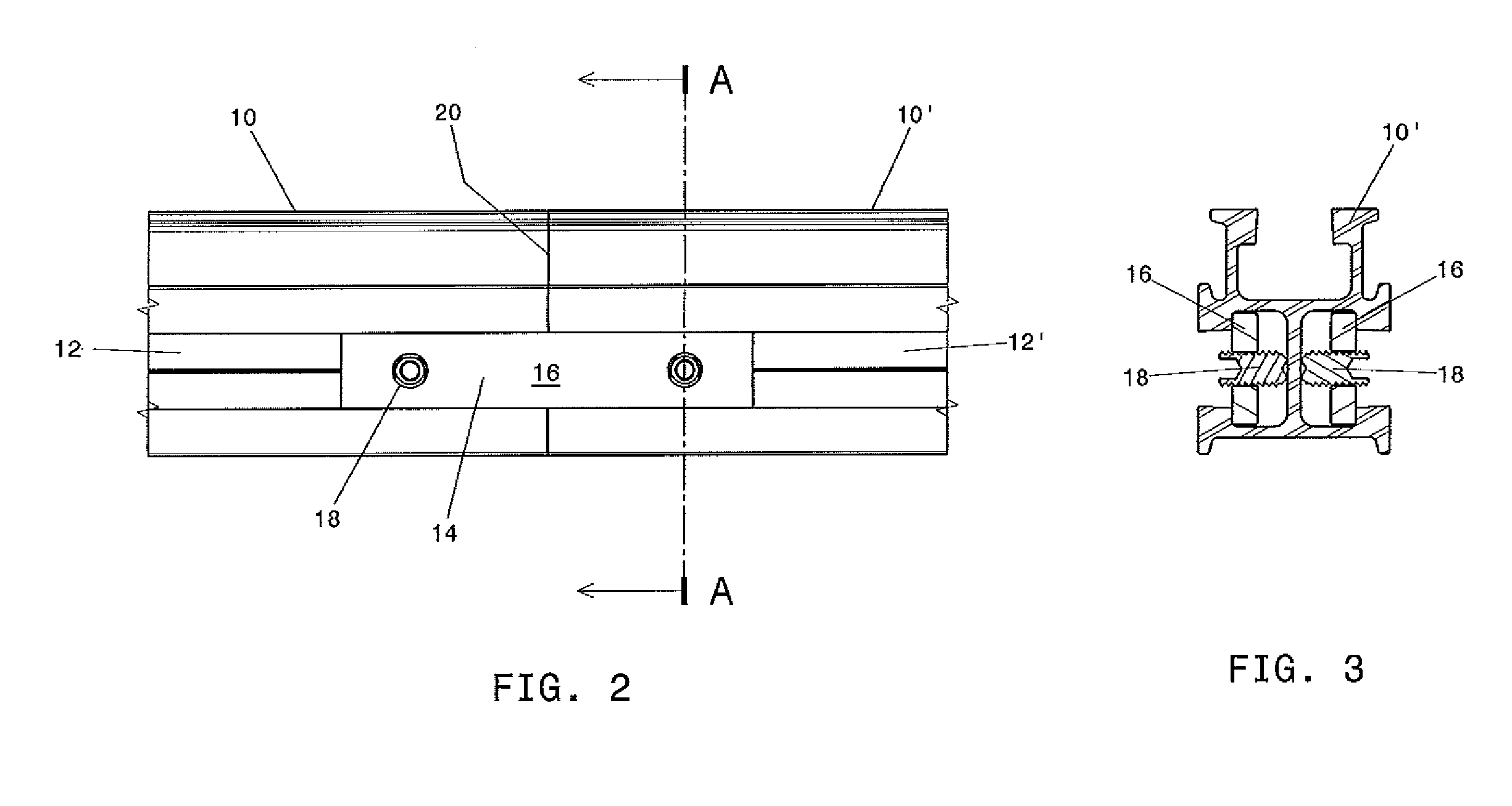
[0039]FIG. 2 is a side view of the rail 10 shown in FIG. 1. Rails 10, 10′ are shown joined with a splice kit 14. FIG. 3 is...


PUM


Abstract

Mounting systems for mounting solar panels to a surface are disclosed and can include panel clamp assemblies and rail clamp assemblies. Panel clamp assemblies can comprise a panel clamp having a base and arms extending from edges of the base, the base having an aperture, a rail clamp having a central portion with an aperture and two flexible tabs extending from the central portion on opposing sides of the aperture and a fastener threaded through the apertures such that that flexible tabs contact a head of the fastener and the arms extend in an opposite direction from the flexible tabs. Rail clamp assemblies can comprise a base member having a bottom and two side walls, the bottom having at least one aperture and each side wall having an elongated aperture, two clamping members and a fastener, wherein the side walls of the base member are positioned such that the opening is of sufficient size to receive the rail.

Description

CROSS-REFERENCE TO RELATED APPLICATION[0001]This application claims priority to U.S. Provisional Patent Application No. 61 / 174,505, filed May 1, 2009, the entire contents of which is incorporated herein by reference.FIELD OF THE INVENTION[0002]The present invention relates in general to ground and roof mounting systems for solar panels and in particular, unique attachment means for attaching solar panels to the racking systems.BACKGROUND[0003]Solar panels are becoming an increasingly useful means of providing renewable energy for commercial and residential properties. Mounting solar panels correctly can contribute to maximizing energy production. The mounting of the solar panels also contributes to protecting the solar panels from the force of wind. The proper solar panel mounting provides stability and determines the directional and latitudinal orientation of the solar array. Solar panels can be mounted on the roof, the ground, or on a pole, for example. The different mounting syst...

Claims


Application Information

Patent Timeline
IPC IPC(8): F16M13/02F16M13/00F16B2/02
CPCF16B7/0486F16B9/023F24J2/5205F24J2/5232F24J2/5245Y10T24/44017F24J2/526F24J2002/4672F24J2002/5216F24J2002/5226Y02E10/47F24J2/5258F24S25/61F24S2025/6008F24S2025/803F24S2025/807F24S25/33F24S25/65F24S25/12F24S2025/802F24S25/636F16B2200/509
Inventor FAUST, AARONHARBERTS, JOHN HENRYKLINKMAN, JOHN EDWARDKATT, RONALD PAULRAFFLER, DAVID WAYNE
Owner APPLIED ENERGY TECH
Why Eureka
Try Eureka