
Stackable plant pot

a plant pot and planter technology, applied in the field of plant pots, can solve the problems of not being able to be hung or suspended, the arrangement of plant pots is not adapted to be used in any suitable manner, and the design and construction of each individual pot is quite complex

Inactive Publication Date: 2010-11-18
KEATS JOHN RODNEY
View PDF2 Cites 24 Cited by
  • Summary
  • Abstract
  • Description
  • Claims
  • Application Information

AI Technical Summary

Benefits of technology

"The invention is a plant pot that can be stacked with other plant pots. It has a cavity with a water reservoir region and a soil holding region. There is an overflow outlet in the reservoir region to prevent excess water from flowing out of the pot. The plant pot also has separation means to separate the water reservoir region from the soil holding region. The water reservoir region can be laterally defined by a side wall of the pot or a dam wall. The plant pot can also have soil watering means to transfer water from the water reservoir region to the soil holding region. The plant pot can also have saucer engagement means and centrally located apertures for easy stacking and alignment with a saucer plate. The technical effects of this invention are that it allows for easy stacking and alignment with a saucer plate, and provides a convenient way to water plants from the pot."

Problems solved by technology

Generally, however, such plant pots can not be stacked—one on top of another—in any suitable manner for use.
Also, this arrangement of plant pots is not adapted to be hung or suspended.
Also, the particular design and construction of each individual pot is quite complex and it would be difficult and expensive to manufacture.
This particular arrangement of plant pots is also not adapted to be hung or suspended.
The plant pot of this disclosure is relatively flimsy and the stacking of 3 or more plant pots (especially if they contain soil) is likely to cause the lower pots in the arrangement to collapse or deform.
This arrangement for connecting adjacent pots is awkward for a user, given the relatively small sizes of the corresponding protrusions and slots.
One of the deficiencies in the prior art devices discussed above relates to the watering of plants within a stack of plant pots.
However, a problem with this arrangement is that water in the upper pots is not retained and the water eventually flows down to all of the lower plant pots leaving the upper plant pots with insufficient retained water.
Consequently, the lower plant pots typically end up having too much water whereas the upper pots tend to have too little water.

Method used


Image

  • Stackable plant pot
  • Stackable plant pot
  • Stackable plant pot

Examples


examples

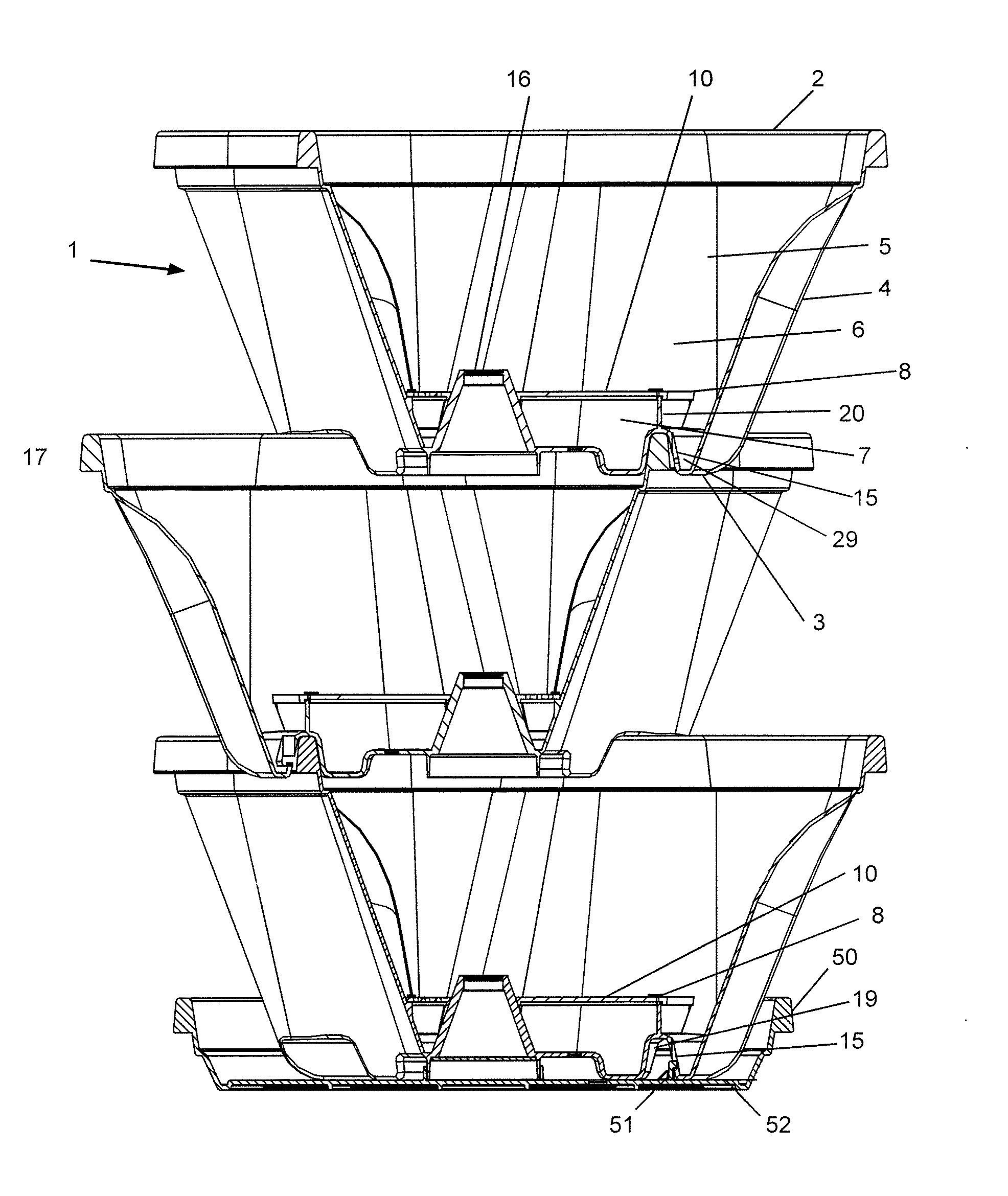
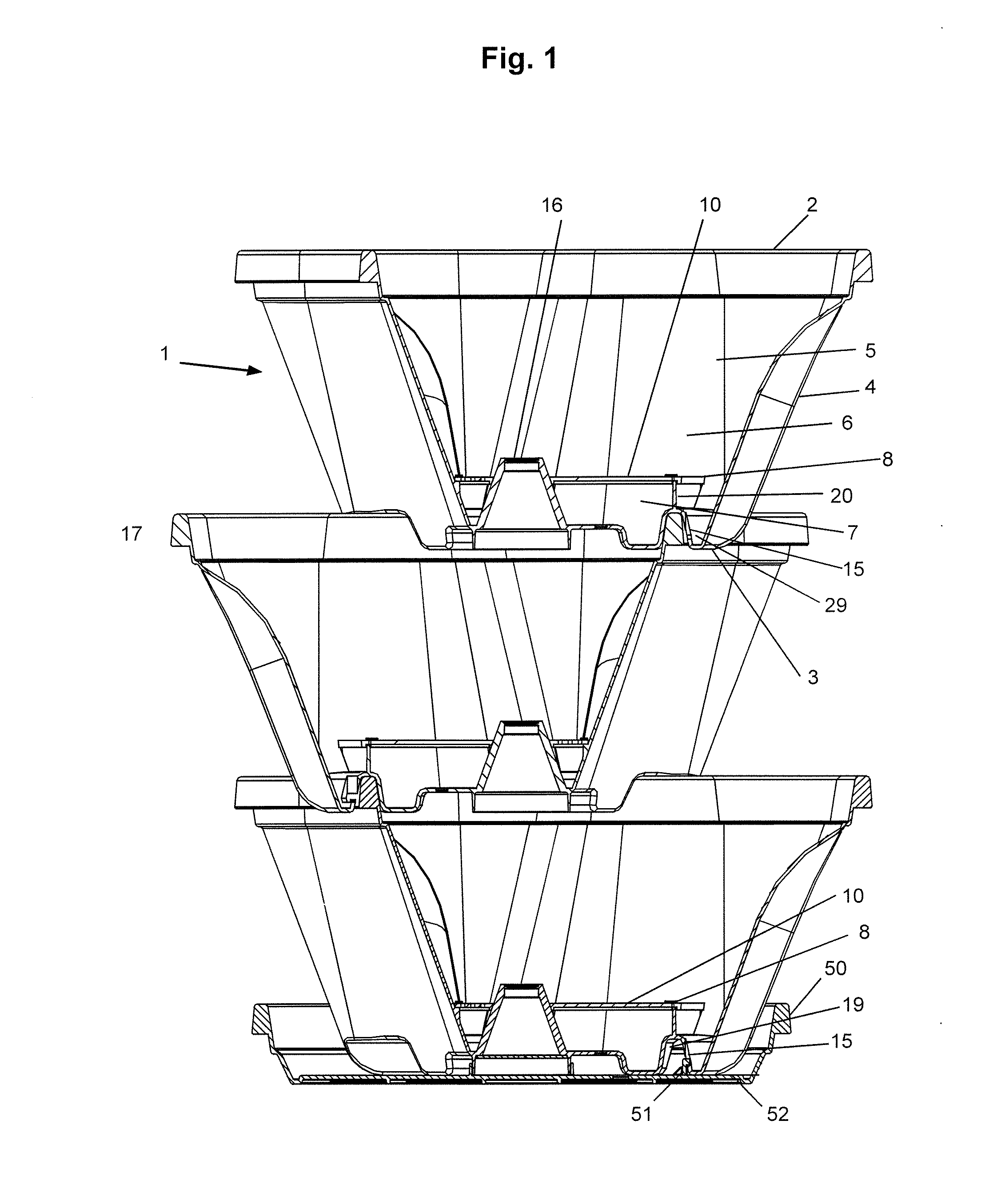
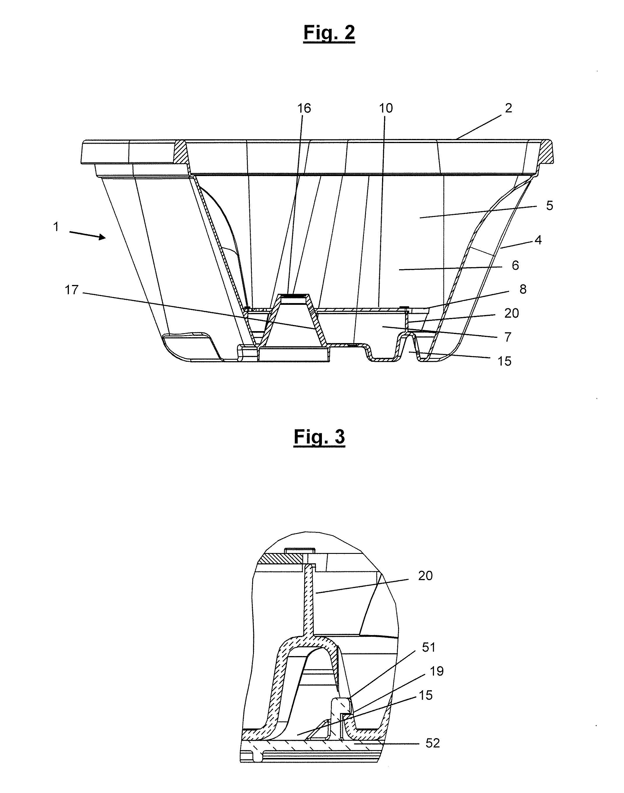
[0092]The drainage system of an embodiment of this invention has been designed to transform the stacked planting arrangement by the selective removal of blind drainage holes to enable it to have a number of uses, including:

[0093](1) Standard Completely Free Draining Planting System—which is useful for plants such as cacti, succulents, orchids and begonia's etc.

[0094]Here the opening of certain ‘blind’ drainage holes, which are located at adjacent a lowermost point of the cavity is desired. The opening of such blind drainage holes helps to ensure that there are no overly moist areas in the plant pots.

[0095](2) A Self-Watering Stacked Planting System—which is useful for all moisture loving plants such as ferns, herbs, and annuals etc.

[0096]Here only the opening of certain other drainage holes is required. These drainage holes are typically located above the base of the cavity so that some water is retained in the cavity. This will allow the cavity (ie water reservoir) to fill and main...


PUM


Abstract

A plant pot which is adapted to be stacked with one or more similar plant pots.

Description

TECHNICAL FIELD[0001]The present invention relates to stackable plant pots and, in particular, to easily waterable stackable plant pots.BACKGROUND[0002]Various forms of plant pots are known for growing plants. Typical plant pots are either of generally cylindrical, frustoconical or rectangular prism form. Frustoconical type plant pots, or other plant pots which are tapered so that the bottom of each pot is narrower than the top, are advantageous over cylindrical or rectangular prism type pots in that they are often able to be located at least partially within each other and thereby able to be stacked for transport, storage and display, thereby realising considerable space savings. Generally, however, such plant pots can not be stacked—one on top of another—in any suitable manner for use. Many pot plant enthusiasts like to arrange several pots in a generally vertical relationship for particular aesthetic appeal and saving of space. Such an arrangement currently typically depends on u...

Claims


Application Information

Patent Timeline
Patent Type & Authority Applications(United States)
IPC IPC(8): A01G9/02
CPCB65D21/043A01G9/023B65D85/52
Inventor KEATS, JOHN RODNEY
Owner KEATS JOHN RODNEY
Learn More