Conveyor Apparatus

a conveyor and hopper technology, applied in the direction of mechanical conveyors, conveyor parts, loading/unloading, etc., can solve the problems of increasing the cost of such machines, increasing the degradation and spillage of the conveyor, and complicating the receiving hopper

Active Publication Date: 2010-11-18
FLSMIDTH RAHCO +1
View PDF26 Cites 66 Cited by
  • Summary
  • Abstract
  • Description
  • Claims
  • Application Information

AI Technical Summary

Benefits of technology

[0006]A conveyor apparatus is provided that includes a tail portion moveably connected to a head portion such that the head portion is moveable relative to the tail portion from a first position to a second position located lower or higher than the first position. The conveyor apparatus also includes at least one frame portion moveably positioned between the tail portion and the head portion such that the one or more frame portions move when the head portion moves from the first position to the second position.

Problems solved by technology

Many types of luffing conveyors are configured to move the whole conveyor, which complicates its receiving hopper and can substantially increase the cost of such machines.
As a result, material may fall from an undesirably high height, which increases degradation and spillage.

Method used


Image

  • Conveyor Apparatus
  • Conveyor Apparatus
  • Conveyor Apparatus

Examples


Embodiment Construction

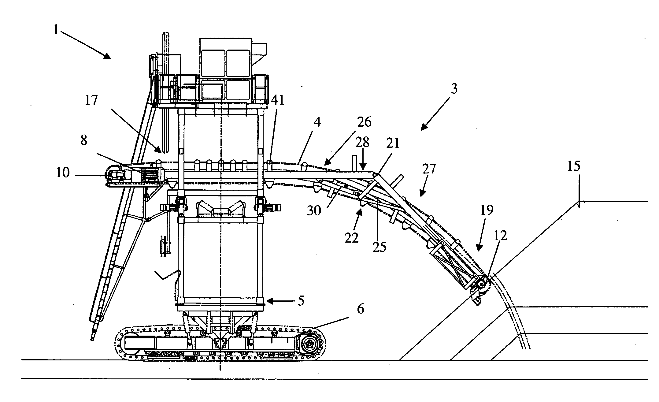
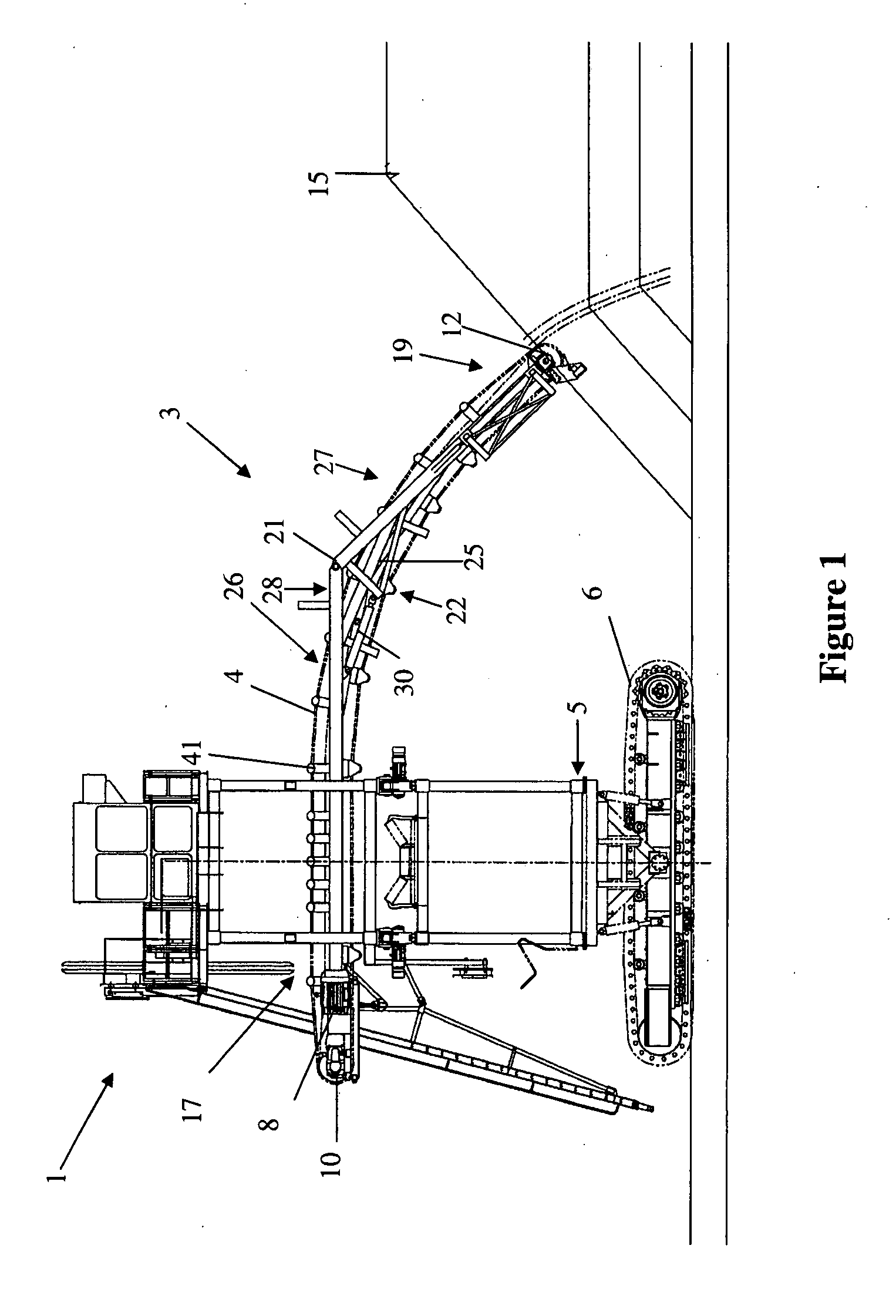
[0031]Referring to FIG. 1, a present preferred embodiment of a stacker 1 that includes a present preferred embodiment of a conveyor apparatus 3 is shown. The stacker 1 has a base 5 that includes tracks 6 configured to move the stacker 1. The base 5 of the stacker also supports the conveyor apparatus 3.

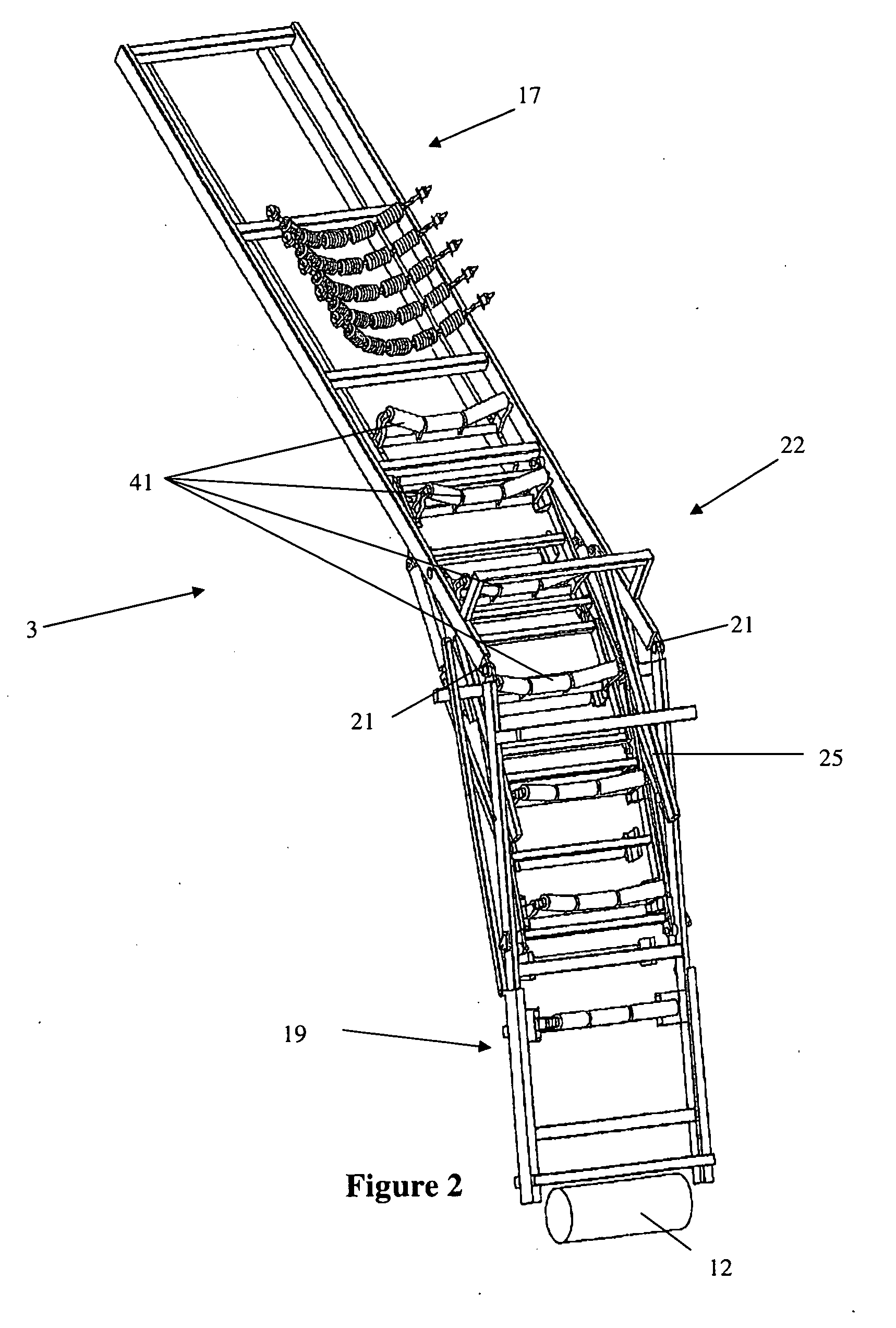
[0032]The conveyor apparatus 3 includes a belt 4 or other flexible elongated member configured to rotate about the conveyor apparatus. A belt drive 8 or other motor is provided adjacent to the tail portion 17 of the conveyor apparatus. A drive pulley 10 is connected to the belt drive 8 and rotates to move the belt 4. A belt pulley 12 is provided adjacent to a head portion 19 of the conveyor apparatus 3. The belt pulley rotates to help the conveyor belt rotate about the head portion 19 of the conveyor apparatus. The conveyor apparatus 3 includes a number of idlers 41 positioned along the conveyor apparatus 3. The idlers engage the belt 4 and help guide the movement of the belt 4.

[0033]A...


PUM


Abstract

A conveyor apparatus includes a tail portion connected to a head portion such that the head portion is moveable relative to the tail portion from a first position to a second position located lower than the first position. It should be appreciated that such movement of the head portion can permit the drop height of the conveyor apparatus to be adjusted. At least one frame portion is moveably positioned between the tail portion and the head portion. A stacker is also provided that includes the conveyor apparatus.

Description

FIELD OF THE INVENTION[0001]The present invention relates to material handling and, more particularly, to stackers and conveyors.BACKGROUND OF THE INVENTION[0002]Conveyors are used to discharge material at a fixed height above ground to stack material such as agglomerated material, ore, or minerals. Such conveyors are typically included in stackers or other devices used to discharge material at a fixed height. U.S. Pat. Nos. 3,185,290, 4,029,200, 4,245,732, 4,406,361, 4,629,060, 4,907,932, 5,181,600, 6,360,876, and 6,896,123 disclose different types of conveyor apparatuses or stackers.[0003]Some conveyed materials such as agglomerated ore are sensitive to drop height. Often, luffing conveyors are used to reduce the drop height of the material. Reducing the drop height can help reduce degradation or spoilage of the material being stacked. Many types of luffing conveyors are configured to move the whole conveyor, which complicates its receiving hopper and can substantially increase th...

Claims


Application Information

Patent Timeline
Patent Type & Authority Applications(United States)
IPC IPC(8): B65G37/00B65G65/06
CPCB65G65/28B65G21/10
Inventor SCHAFER, SCOTT D.
Owner FLSMIDTH RAHCO
Why Eureka
Try Eureka