This helps you quickly interpret patents by identifying the three key elements:
Problems solved by technology
Method used
Benefits of technology
Benefits of technology
[0011]The present invention completely eliminates this source of inaccuracy via the selection of a different test point, development of the test for excitation of oscillation in the selected test point, and designing the tuning rules that account for the phase shift due to the controller introduction. Therefore, the proposed test and tuning rules ensure that either the specified gain margin of the system or the specified phase margin of the system will be provided. The present invention defines a method and an apparatus for bringing the system (comprising the pr
Problems solved by technology
Despite the apparent success of relay based tuning, it can lead to reduced or vice versa excessively large gain and phase margins because of the choice of the test point (frequency of the oscillations) corresponding to the phase lag of the process equal to −180° (phase cross-over frequency ωπ) while inclusion of the controller in the loop introduces additional phase shift, which was not accounted for at the selection of the test point and designing the tuning rules.
Method used
Image
Click on the blue label to locate the original text in one second.
Reading with bidirectional positioning of images and text.
Examples
example 2
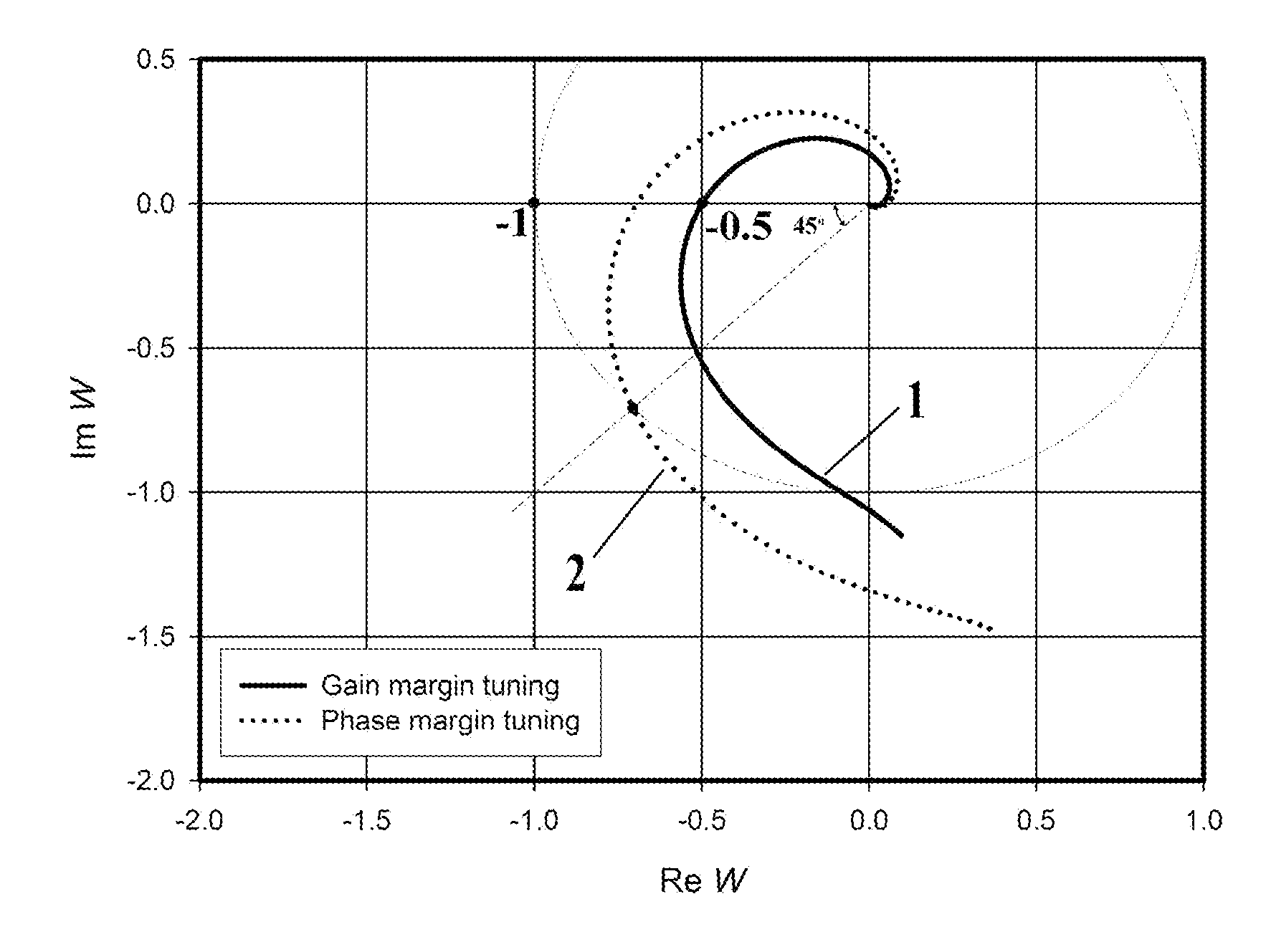
[0039]Consider the process transfer function (1) that was used in Example 1. (a) Apply the modified RFT with amplitude h=1, parameter)β=0.195 and c1, c2 values from Table 1 for tuning a PI controller with specification on gain margin γm=2. (b) After that use the modified RFT with amplitude h=1, parameter)β=0.659 and c1, c2 values from Table 2 for tuning a PI controller with specification on phase margin φm=45°. The controller tuning that is done according to the presented method produces the following results. (a) The modified RFT gives Ω0=0.188 and α0=0.393; for tuning with specification on gain margin the controller parameters calculated per (12) are Kc=0.978, Tic=26.74; (b) The modified RFT gives Ω0=0.133 and α0=0.544; for tuning with specification on gain margin the controller parameters calculated per (12) are Kc=1.416, Tic=37.85. The frequency response (Nyquist plots) of the open-loop systems for the system tuned with specification on gain margin 1 and for the system tuned wit...
PUM
Abstract
In tuning a PID controller for a process in a feedback controlsystem, a method is provided for bringing the system into symmetric self-excited oscillations for measuring the frequency and the amplitude of the oscillations, and tuning the controller in dependence on the measurements obtained. A control algorithm (modified relay feedback test) is introduced into the system in series with the process to excite self-excited oscillations in the system. Data and formulas are given for the computation of the specific parameter of the modified relay feedback test and for tuning the parameters of the PID controller. An apparatus for performing the method is disclosed.
Description
CROSS-REFERENCE TO RELATED APPLICATIONS[0001]U.S. Patent Documents:4,214,300July, 1980Barlow et al.364 / 105.4,549,123October, 1985Hagglund et al.364 / 157.4,602,326July, 1986Kraus364 / 158.4,754,391June, 1988Suzuki364 / 157.4,836,319June, 1989Haseda et al.180 / 142.Re33267July, 1990Kraus364 / 158.5,124,626June, 1992Thoen364 / 161.5,222,022June, 1993Adams et al.364 / 431.5,223,778June, 1993Svarovsky et al.364 / 157.5,229,699July, 1993Chu et al.364 / 162.5,283,729February, 1994Lloyd364 / 157.5,311,421May, 1994Nomura et al.364 / 157.5,325,288June, 1994Satou364 / 162.5,396,415March, 1995Konar et al.364 / 162.5,412,557May, 1995Lauw363 / 37.5,453,925September, 1995Wojsznis et al.364 / 157.5,535,117July, 1996Hiroi364 / 158.5,568,377October, 1996Seem et al.364 / 157.5,587,899December, 1996Ho et al.364 / 157.5,587,896December, 1996Hansen et al.700 / 285,742,503April, 1998Yu700 / 427,035,695April, 2006Boiko700 / 287,249,882July, 2007Lin374 / 101Other References[0002]Cheng et al., 1999, Identification and Control of Nonlinear Systems Usi...
Claims
Application Information
Patent Timeline
Application Date:The date an application was filed.
Publication Date:The date a patent or application was officially published.
First Publication Date:The earliest publication date of a patent with the same application number.
Issue Date:Publication date of the patent grant document.
PCT Entry Date:The Entry date of PCT National Phase.
Estimated Expiry Date:The statutory expiry date of a patent right according to the Patent Law, and it is the longest term of protection that the patent right can achieve without the termination of the patent right due to other reasons(Term extension factor has been taken into account ).
Invalid Date:Actual expiry date is based on effective date or publication date of legal transaction data of invalid patent.

