Flow Rate Detection Method and Flow Rate Detection Apparatus Using a Heat Signal

a flow rate detection and flow rate detection technology, applied in the direction of fluid speed measurement, fluid speed measurement using thermal variables, instruments, etc., can solve the problems of large measurement error and addition of errors, and achieve accurate measurement, eliminate sources of error caused by temperature change in the medium, and accurately measure

Inactive Publication Date: 2009-01-29
SURPASS IND
View PDF6 Cites 22 Cited by
  • Summary
  • Abstract
  • Description
  • Claims
  • Application Information

AI Technical Summary

Benefits of technology

[0010]The present invention has been conceived in light of the problems described above, and it is an object of the present invention to provide a flow rate detection method and a flow rate detection apparatus that are capable of accurate flow rate measurement without any measurement error by using a heat signal.
[0024]Consequently, a significant advantage is obtained; namely, a flow rate detection method and a flow rate detection apparatus in which sources of measurement errors are eliminated and which are able to measure an accurate traveling speed (flow rate) are provided.

Problems solved by technology

With the above-described related art, however, the following sources of error are added to the actual traveling time because the flow rate is determined by detecting the phase difference or time difference from a driving (heating / cooling) signal for the heating element or a temperature signal detected at the temperature sensor downstream and by taking into consideration a distance L1 between the heating element and the temperature sensor.
As a result, it is clear that the times Ta, Tb, and Td added to the fluid traveling time Tc cause error tending to decrease the detected traveling velocity Va compared with the actual traveling velocity V. Such a measurement error becomes particularly large when the traveling velocity V increases.

Method used


Image

  • Flow Rate Detection Method and Flow Rate Detection Apparatus Using a Heat Signal
  • Flow Rate Detection Method and Flow Rate Detection Apparatus Using a Heat Signal
  • Flow Rate Detection Method and Flow Rate Detection Apparatus Using a Heat Signal

Examples


first embodiment

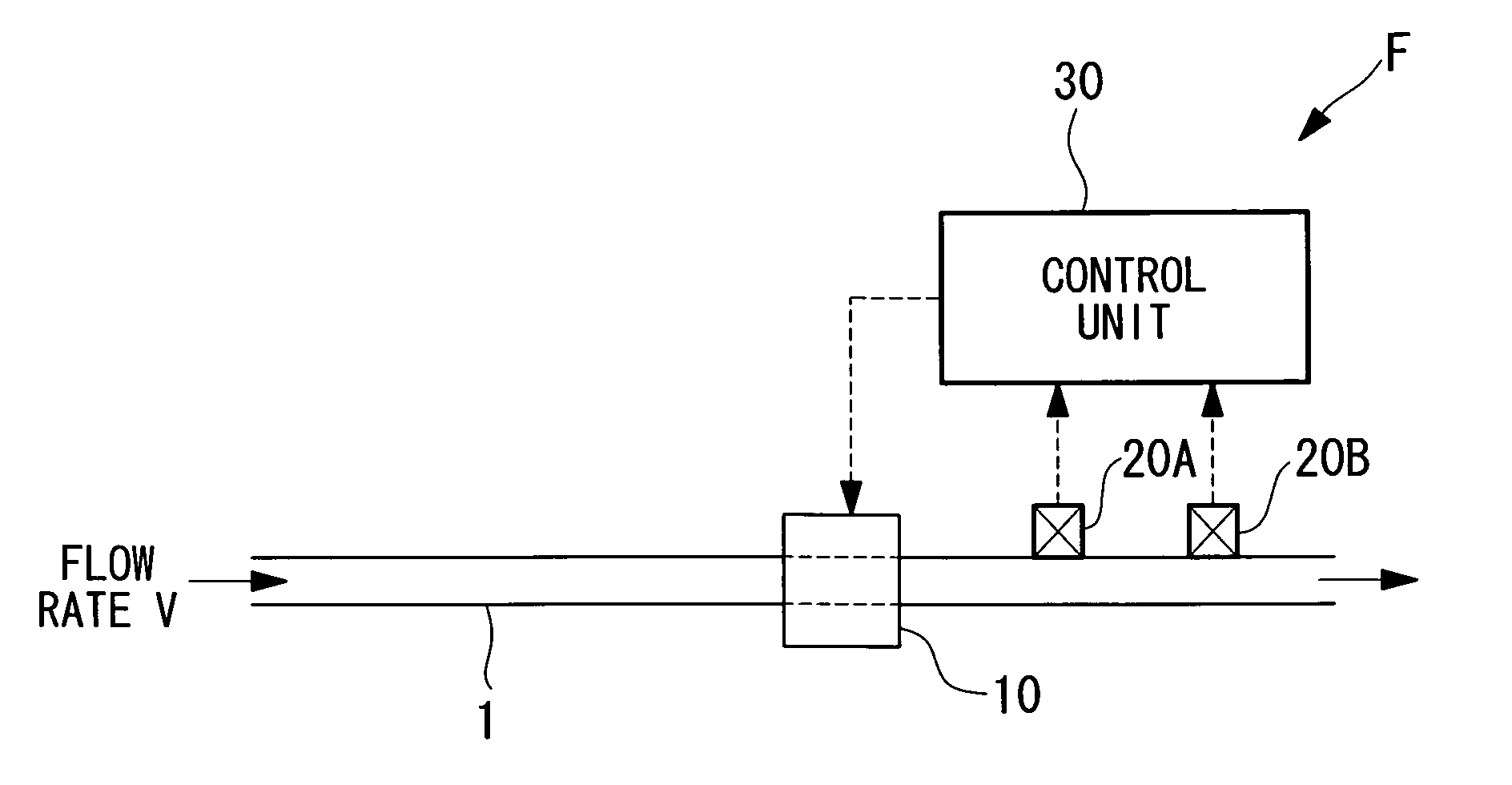
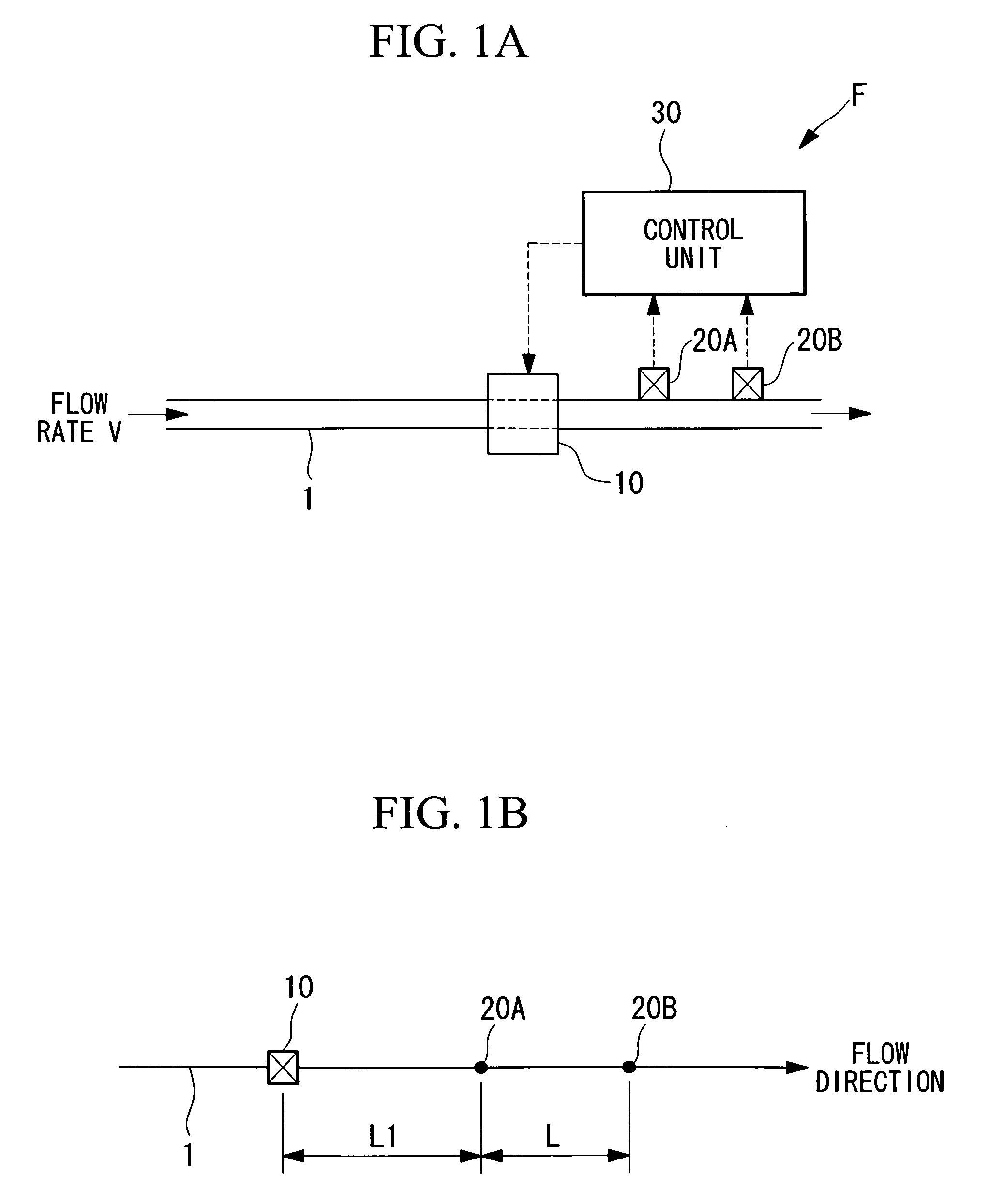
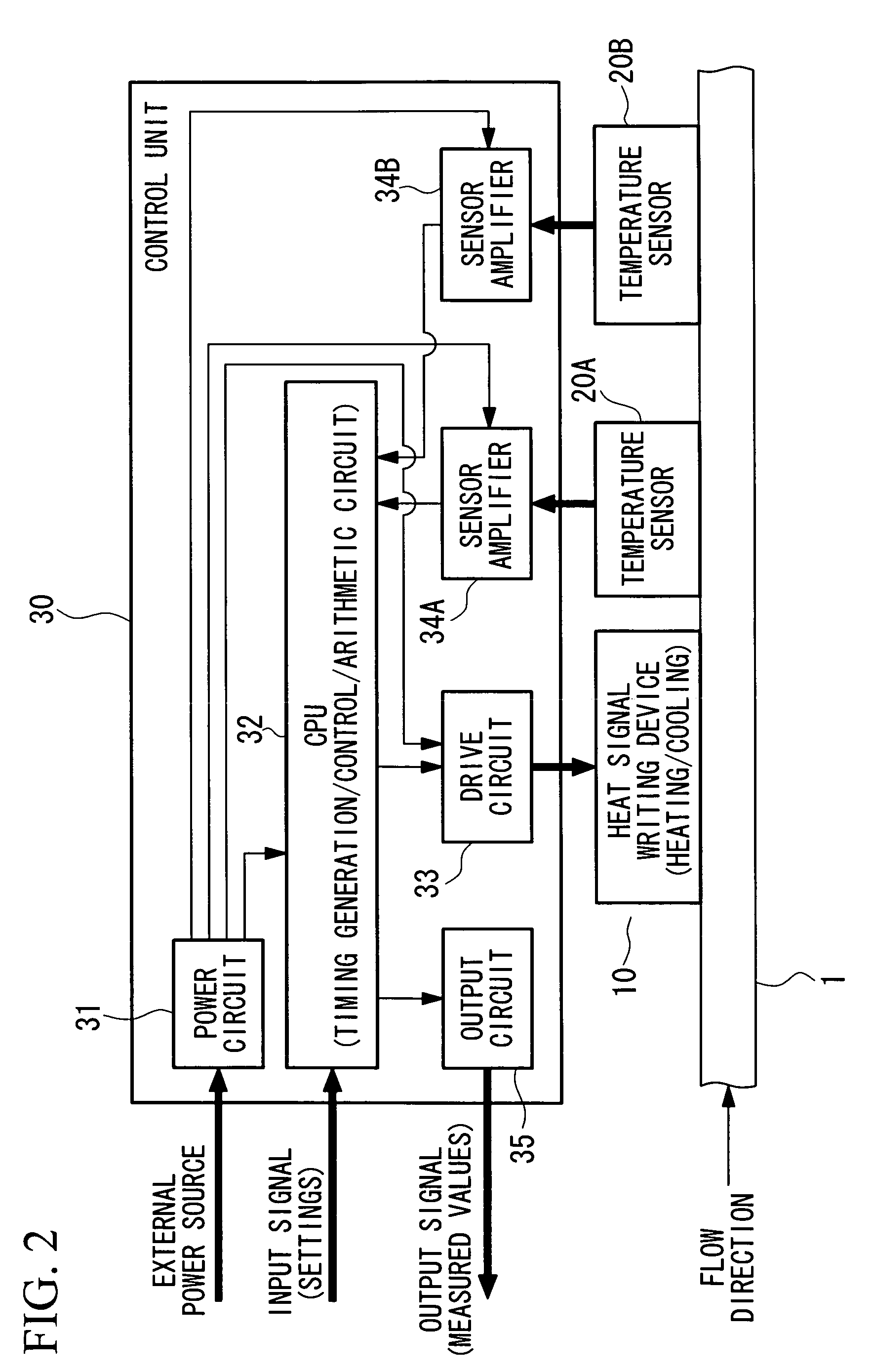
[0041]In a first embodiment shown in FIGS. 1A to 3B, a flow-rate detector F includes a heat signal writing device 10 which is provided at an appropriate position in a channel 1 and which writes a heat signal; a first temperature sensor 20A for detecting the written heat signal at a position away from the heat signal writing device 10; a second temperature sensor 20B which is disposed a predetermined distance L away from the first temperature sensor 20A and which detects the heat signal written by the heat signal writing device 10; and a control unit 30 that is electrically connected to the heat signal writing device 10, the first temperature sensor 20A, and the second temperature sensor 20B via wires.

[0042]The heat signal writing device 10 is secured at an appropriate position in the channel 1 through which a medium flows at a flow rate v and constitutes heat-signal writing means for writing a heat signal in the medium flowing through the channel 1. The heat signal writing device 10...

second embodiment

[0062]A second embodiment of the present invention will be described with reference to FIGS. 4 to 7. The components that are the same as those according to the above-described first embodiment will be represented by the same reference numerals, and descriptions thereof will be omitted.

[0063]As shown in FIG. 4, according to this embodiment, a medium temperature sensor 40 is provided, at an appropriate position in the channel 1 upstream of the heat signal writing device 10, as medium-temperature detecting means for detecting the temperature of a medium before writing a heat signal. The medium temperature sensor 40 is electrically connected to a control unit 30A via a wire. A sensor amplifier 36 that amplifies a value detected at the medium temperature sensor 40 and that inputs this value to a CPU 32A is additionally provided inside the control unit 30A.

[0064]By providing such a medium temperature sensor 40, the control unit 30A outputs a control signal from the CPU 32A to the drive ci...


PUM


Abstract

A flow rate detection method using a heat signal that enables accurate flow rate measurement by eliminating sources of measurement error is provided. The flow rate detection method, using a heat signal, of writing a temperature-change heat signal in a medium traveling through a channel and detecting the heat signal with heat signal detecting means provided at a position away from the writing position, to measure a traveling speed of the medium, wherein first and second temperature sensors 20A and 20B, which are separated by a predetermined distance L, are disposed downstream of the writing position, and the traveling speed is calculated from a time difference at which the two temperature sensors 20A and 20B detecting the heat signal and from the distance L.

Description

TECHNICAL FIELD[0001]The present invention relates to a flow rate detection method and a flow rate detection apparatus for detecting the traveling velocity (flow rate) of a fluid using a heat signal in the form of a temperature change in the fluid.BACKGROUND ART[0002]Thermal flowmeters for measuring the mass flow of a liquid using heat have been proposed in the past. In this case, heat is used to a detect temperature change, a temperature difference between two points, or a time difference in a temperature change etc.[0003]A heat-transfer fluid detecting apparatus for measuring the angular velocity and the flow rate of a fluid acting in a channel on the basis of a change in the traveling time of heat through a fluid serving as a medium has been proposed. With this apparatus, the fluid flowing through the channel is heated by an AC-driven heating element, and the heat transferred by this fluid is detected by a heat sensor provided downstream. In this way, the angular velocity can be ...

Claims


Application Information

Patent Timeline
Patent Type & Authority Applications(United States)
IPC IPC(8): G01F1/68G01F1/7084
CPCG01F1/6847G01P5/18G01P5/12G01F1/7084G01F1/704G01F1/708
Inventor IMAI, HIROSHIMATSUSHIMA, KEIICHIUSHIGUSA, YOSHIHIRO
Owner SURPASS IND
Why Eureka
Try Eureka