
Injector for gas fuel

A gaseous fuel and injector technology, which is applied in fuel injection devices, charging systems, combustion engines, etc., can solve the problems of flow drop and aperture narrowing, and achieve the effects of accurate fuel injection, accurate flow measurement, and excellent stripping properties

Inactive Publication Date: 2012-09-19
NIKKI CO LTD
View PDF5 Cites 4 Cited by
  • Summary
  • Abstract
  • Description
  • Claims
  • Application Information

AI Technical Summary

Problems solved by technology

[0004] However, in the above-mentioned fuel passage 9, especially when the orifice 14 part is formed narrow and the inner surface is generally formed of a stainless steel sheet, there is a problem that dust and tar are mixed with the fuel from upstream. Foreign matter such as foreign matter, the above foreign matter adheres to the inner surface and narrows the pore size, resulting in a decrease in flow rate

Method used


Image

  • Injector for gas fuel
  • Injector for gas fuel
  • Injector for gas fuel

Examples


Embodiment Construction

[0024] Hereinafter, preferred embodiments of the present invention will be described in detail with reference to the drawings.

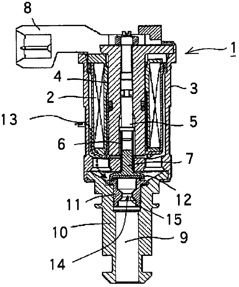
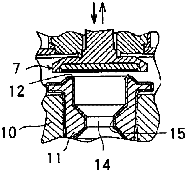
[0025] figure 1 is a schematic diagram of the injector of the present invention, figure 2 It is an enlarged view showing the main part of the injector. The overall structure of the injector is the same as that of the conventional injector. The flow rate regulator is arranged at the center of the coil holder 4 that holds the electromagnetic coil 2 and is embedded in the outer casing 3. Screw 5, at the lower end of the flow regulating screw 5, an injector spool 7 capable of reciprocating along the axial direction is disposed via a spring body 6, and in this injector, a wire connected to a connector 8 (not shown) ) receives instructions from the ECU (not shown), and makes the electromagnetic coil 2 turn on and off according to the instructions, so that the injector spool 7 lifts, and the injector spool 7 is in contact with the injection valve seat 11...


PUM


Abstract

The invention relates to an injector for gas fuel, which can prevent foreign matters, such as dust, tar mixed into the gas fuel from being adhered on a throttle hole part arranged in a fuel through hole to measure the flow of the gas fuel, thereby preventing the flow of the gas fuel from being reduced. In the injector for gas fuel, an injector valve core (7) ascends and descends along the axle direction, thereby contacting with and separating from a valve seat (11) kept by a valve seat keeping piece (10), thus the fuel from a fuel inlet (13) is intermittently sent to the fuel through hole (9) in a preset interval, wherein the valve seat keeping piece (10) comprises the fuel through hole (9) opposite to the lower surface of the injector valve core (7), and moreover, in the injector for gas fuel, the throttle hole (14) for measuring the flow of the gas fuel is arranged in the fuel through hole (9), and a coating layer (15) made of an Ni-P coating film containing fluoro resin particles is coated on the inner surface of the throttle hole (14).

Description

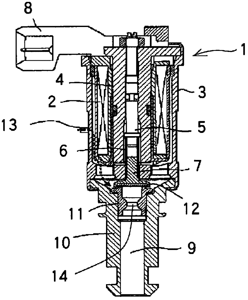
technical field [0001] The present invention relates to an injector for injecting gaseous fuel such as LPG into an intake passage of an internal combustion engine. Background technique [0002] Conventionally, there is known a kind of gas fuel used in internal combustion engines such as LPG image 3 and Figure 4 Shown is an injector that continuously injects a prescribed amount of fuel gas into the intake passage at prescribed intervals. In addition, it is known that the injector 1 is provided with a flow rate adjustment screw 5 at the center of the coil holder 4 that holds the electromagnetic coil 2 and is embedded in the outer casing 3. At the lower end of the flow rate adjustment screw 5, a spring body 6 is interposed therebetween. An injector spool 7 that can reciprocate along the axial direction is configured, and in this injector, an instruction from an ECU (not shown) is received through a wire (not shown) connected to a connector 8, and according to the instruction...

Claims


Application Information

Patent Timeline
Patent Type & Authority Applications(China)
IPC IPC(8): F02M21/02F02M51/06
CPCY02T10/32Y02T10/30F02M21/0251F02M61/042F02M61/166
Inventor 井上透福冈智昭
Owner NIKKI CO LTD
Learn More