Computer system for controlling allocation of physical links and method thereof

a computer system and physical link technology, applied in the field of physical link computers, can solve the problems of affecting the throughput of the sas drive, the time occupied by the physical link is longer, and the transfer efficiency of sata is inferior to the transfer efficiency of sas, so as to prevent a drop in the throughput of the computer system

Inactive Publication Date: 2007-09-20
HITACHI LTD
View PDF8 Cites 83 Cited by
  • Summary
  • Abstract
  • Description
  • Claims
  • Application Information

AI Technical Summary

Benefits of technology

[0017] Therefore, an object of the present invention is to prevent a drop in the throughput of the computer system as much as possible even when there is a concentration of access to a specified SAS target device (e.g. SAS drive, SATA drive, and so on) among a plurality of SAS target devices. This object is preferably implemented without violating the restrictions of the communication protocol of the backend.

Problems solved by technology

A characteristic problem can arise with this storage system in each of the first and second cases below, for example.
Here, SATA and SAS have different transfer efficiencies (specifically, the transfer efficiency of SATA is inferior to the transfer efficiency of SAS and the time occupied by the physical link is longer).
As a result, when there are a large number of SATA-frame I / O transfer requests, there is the possibility of an adverse effect on the throughput with respect to the SAS drive.
A problem of this kind is not limited to these two types of I / F and can also exist between I / Fs of other types.
As a result, when access to a specified RAID group increases, there is the possibility of an adverse effect on the throughput of the other RAID groups.
The above problems are not limited to storage systems and can also exist in other types of computer system.
Furthermore, the procedure for selecting a physical link for executing a frame transfer from a plurality of physical links that constitute a wide link based on the restrictions of protocols such as SAS cannot be controlled by an SAS initiator device.

Method used


Image

  • Computer system for controlling allocation of physical links and method thereof
  • Computer system for controlling allocation of physical links and method thereof
  • Computer system for controlling allocation of physical links and method thereof

Examples


Embodiment Construction

[0066] A storage system in which a computer system according to a first embodiment of the present invention will be described hereinbelow by way of example with reference to the drawings.

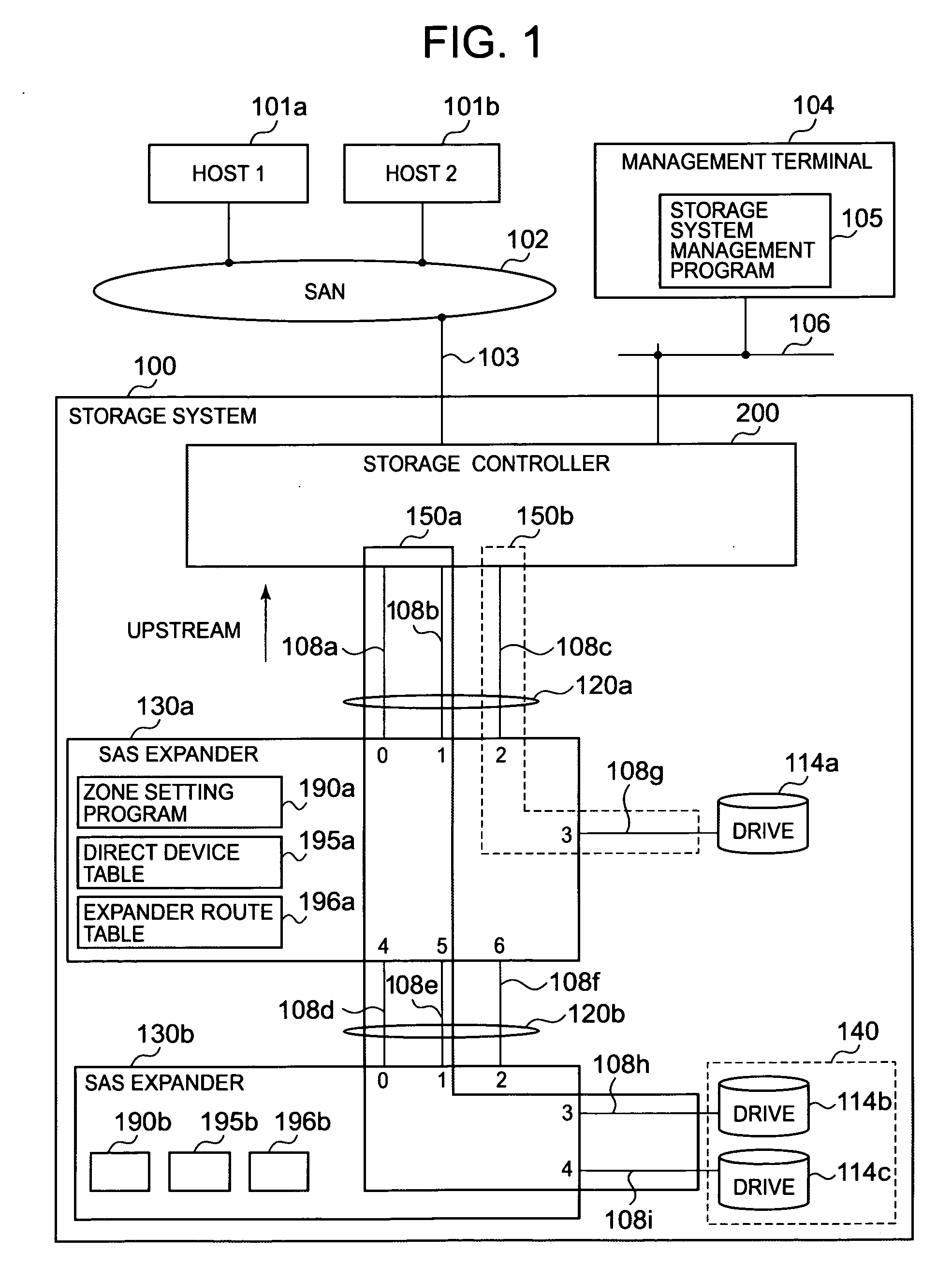
[0067]FIG. 1 is a block diagram showing a constitutional example of the storage system of a first embodiment of the present invention. The description is provided hereinbelow by adding the same parent numbers to elements of the same type and adding child numbers to the parent numbers when elements of the same type are described individually.

[0068] A storage system 100 can be connected by an interface 103 such as an FC (Fiber Channel), a SCSI (Small Computer System Interface), SAS (Serial Attached SCSI), or IP (Internet Protocol) to a SAN (storage area network) 102 to which one or a plurality (two, for example) of host computers 101a and 101b are connected. Further, the storage system 100 can also be connected to a management network 106 to which a management terminal 104 is connected, for example....


PUM


Abstract

The computer system of the present invention has a plurality of SAS target devices, an SAS initiator device, and a service delivery subsystem that is connected to each SAS target device by means of a physical link that is physical wiring and connected to the SAS initiator device by means of a wide link constituted by a plurality of physical links. The SAS initiator device controls how many physical links in the wide link are allocated to a particular SAS target device, whereby access from the SAS initiator device to the SAS target device is made via a physical link that is allocated to the SAS target device and is not made via a physical link that is not allocated to the SAS target device.

Description

CROSS-REFERENCE TO PRIOR APPLICATION [0001] This application relates to and claims priority from Japanese Patent Application No. 2006-76505, filed on Mar. 20, 2006 the entire disclosure of which is incorporated herein by reference. BACKGROUND OF THE INVENTION [0002] 1. Field of the Invention [0003] The present invention relates to a computer system comprising physical links, and more specifically, to a computer system in which physical links for SAS (Serial Attached SCSI)-compliant communications are provided in the backend, for example. [0004] 2. Description of the Related Art [0005] A storage system that comprises a plurality of storage devices (disk drives such as hard disk drives and DVD (Digital Versatile Disk, for example) is known as one type of computer system. A storage system is capable of receiving an I / O command (an I / O command constituting a write command or read command) from an access source device (a host computer or other storage system, for example) and of transmit...

Claims


Application Information

Patent Timeline
Patent Type & Authority Applications(United States)
IPC IPC(8): G06F12/16G06F12/00
CPCG06F3/0607G06F3/0613G06F3/0631G06F3/0689G06F3/0637G06F3/0661G06F3/067G06F3/0635
Inventor NAKAJIMA, AKIOYAGISAWA, IKUYA
Owner HITACHI LTD
Why Eureka
Try Eureka