Stage apparatus and exposure apparatus

a stage apparatus and exposure apparatus technology, applied in the direction of dynamo-electric components, instruments, printers, etc., can solve the problems of insufficient margin during the exposure operation, drop in throughput, and great loss of time, so as to prevent a drop in throughput

Inactive Publication Date: 2011-07-05
NIKON CORP
View PDF71 Cites 1 Cited by
  • Summary
  • Abstract
  • Description
  • Claims
  • Application Information

AI Technical Summary

Benefits of technology

Therefore, in the stage apparatus, even in the case where, after the desired process (for example, the liquid supply process) has been performed using the first moving table at the first position, the first moving table has been moved to the second position in conjunction with the movement of the moving stage or with respect to the moving stage, it is possible to continue to perform the desired process using the second moving table positioned at the first position. For this reason, even when the first moving table has moved to the second position, there is no longer a need to stop the desired process, for example, the liquid supply process, and it becomes possible to prevent a drop in throughput.
Therefore, in the stage apparatus, even in the case where, after the desired process (for example, the liquid supply process) has been performed using a first moving table at the first position, the first moving table has moved to the second position by means of the driving of the first moving apparatus or the second moving apparatus, it is possible to continue to perform the desired process using the second moving table positioned at the first position. For this reason, there is no longer a need to stop the desired process, for example, the liquid supply process, even when the first moving table has moved to the second position, and it becomes possible to prevent a drop in throughput.
Therefore, in the exposure apparatus of the present invention, even in the case where, after the pattern has been exposed while performing the desired process (for example, the liquid supply process) on the substrate held on the first moving table at the first position, the first moving table has moved to the second position, it is possible to continue to perform the desired process using the second moving table positioned at the first position. For this reason, there is no longer a need to stop the desired process, for example, the liquid supply process, even when the first moving table has moved to the second position, and it becomes possible to prevent a drop in throughput.
In the some aspects of the present invention, even when the first moving table has moved to the second position, by using the second moving table, there is no longer a need to stop the desired process, and it becomes possible to prevent a drop in throughput.

Problems solved by technology

At such times, when the depth of focus δ is too narrow, it is difficult to match the substrate surface to the image plane of the projection optical system, and there is concern that the margin during the exposure operation will be insufficient.
In addition, after substrate exchange, it is necessary to fill liquid between the projection optical system and the substrate stage, so there are problems in that there is a great loss of time, and throughput drops.
In addition, drying is performed through recovery of the liquid, so there is a problem in that water marks are produced on the projection optical system, and there is a problem in that temperature changes occur in the projection lens, the liquid supply nozzle, etc. due to heat of vaporization.
Therefore, it is thought that even when the substrate stage has been moved to the loading position, the substrate stage (or a liquid immersion region forming member provided on the substrate stage) is made larger so that a liquid immersion region continues to be formed in the space with respect to the projection optical system, but in this case, a problem occurs in that this leads to an increase in the weight of the substrate stage, and throughput drops.
In addition, since it becomes necessary to increase the distance between an interferometer, which is provided to obtain substrate position information, and the movable mirror, this leads to the problems of a larger apparatus and a reduction in measurement accuracy.

Method used


Image

  • Stage apparatus and exposure apparatus
  • Stage apparatus and exposure apparatus
  • Stage apparatus and exposure apparatus

Examples


first embodiment

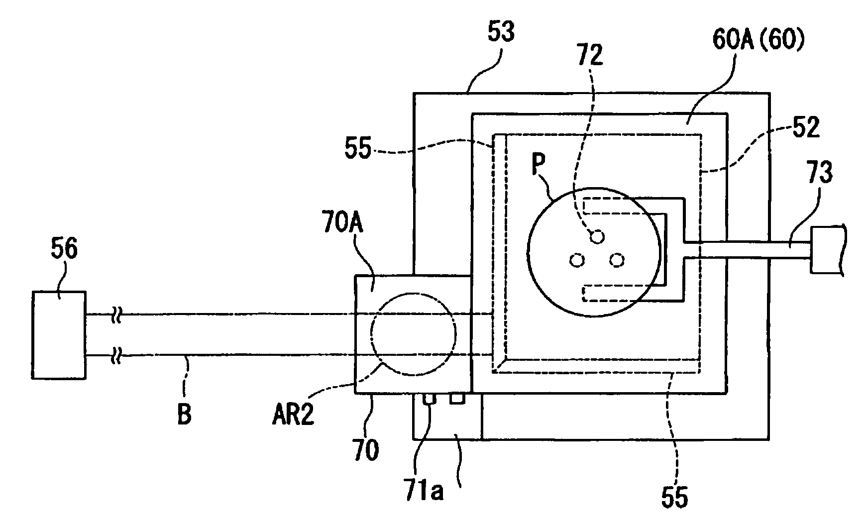
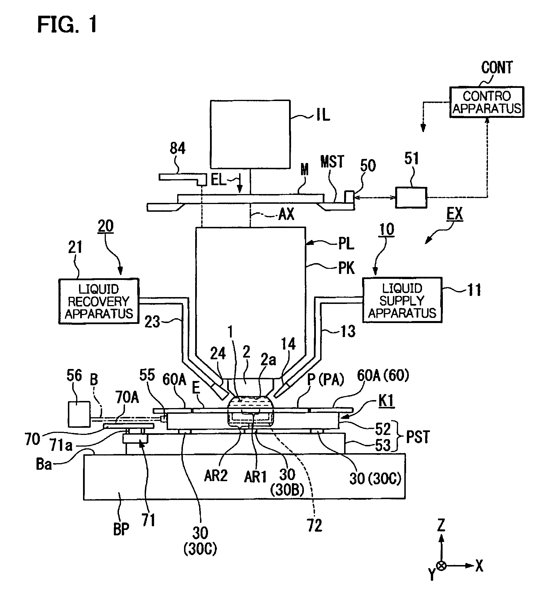
In FIG. 1, the exposure apparatus EX of the present embodiment comprises a mask stage MST that supports a mask M, an illumination optical system IL that uses exposure light EL to illuminate the mask M that is supported by the mask stage MST, and a projection optical system PL that projection exposes the pattern image of the mask M illuminated by the exposure light EL onto the substrate P supported on a substrate stage PST that is the stage apparatus, and the operation of the entire exposure apparatus EX is comprehensively controlled by a control apparatus CONT.

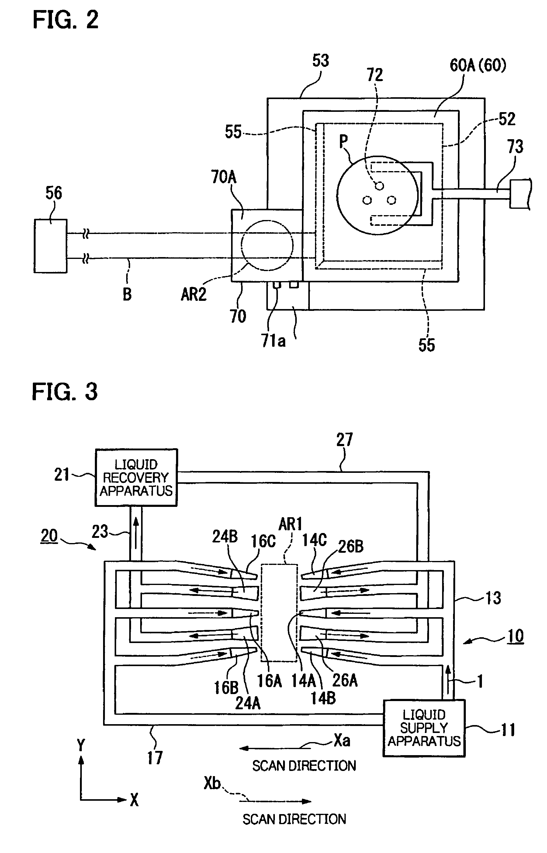
The exposure apparatus EX of the present embodiment is a liquid immersion exposure apparatus that has applied the liquid immersion method to effectively shorten the exposure wavelength to improve resolution as it effectively broadens the depth of focus, and it comprises a liquid supply mechanism (liquid supply apparatus) 10 that supplies a liquid 1 onto the substrate P and a liquid recovery mechanism 20 that recovers the liqui...

second embodiment

Next, a second embodiment of the stage apparatus relating to the present invention will be explained while referring to FIG. 5 to FIG. 12.

The stage apparatus ST in the present embodiment shown in FIG. 5 is a twin stage type apparatus, in which two stages that hold a substrate P have been mounted, and it comprises a first substrate stage PST1 and a second substrate stage PST2 which are able to respectively independently move on a common base BP. In addition, the twin stage type stage apparatus ST comprises an exposure area A (in FIG. 5, the left side), on which a liquid immersion region AR2 is arranged and which performs exposure processing on the substrate P, and a measuring area AL (in FIG. 5, the right side), in which measurement processing relating to the substrate stage PST1 (or PST2) that held the substrate P is performed. Due to the fact that the first substrate stage PST1 and the second substrate stage PST2 move, it is possible to exchange the first substrate stage PST1 and t...

third embodiment

Next, a third embodiment of the stage apparatus ST will be explained while referring to FIG. 13 to FIG. 15. In these figures, reference symbols are assigned to elements that are identical to the constituent elements of the second embodiment shown in FIG. 5 to FIG. 12, and explanations thereof will be omitted or abbreviated.

In the above second embodiment, in a double stage type stage apparatus, a configuration such that a moving table is provided on X coarse movement stage 63A was used, but, in the present embodiment, the configuration is such that the moving table 70 is linked with movers 62A of a Y linear motor 65A that drive the substrate table 52A with a larger stroke than that of the fine movement stage 100A.

Specifically, in the present embodiment, as shown in FIG. 13, a stay 76, which extends in the X direction, is suspended in a horizontal direction between a pair of movers (second moving apparatuses) 62A, 62A that comprise the Y linear motor 65A. The moving table 70 extends o...


PUM


Abstract

A stage apparatus includes: a moving stage, which moves along a movement plane; a first moving table, which holds a specimen while being able to move with respect to the moving stage; and a second moving table, which is provided on the moving stage and, when the first moving table has moved from a first position to a second position, is positioned at the first position.

Description

BACKGROUND OF THE INVENTION1. Field of the InventionThe present invention relates to a stage apparatus and an exposure apparatus; for example, it relates to a stage apparatus and an exposure apparatus that are optimal for use when performing so-called liquid immersion exposure, in which a liquid is supplied onto a substrate to perform exposure.2. Description of Related ArtSemiconductor devices and liquid crystal display devices are manufactured by a so-called photolithography technique that transfers a pattern formed on a mask onto a photosensitive substrate.The exposure apparatus used in this photolithography process has a mask stage that supports a mask and a substrate stage that supports a substrate, and it transfers the pattern of the mask to the substrate via a projection optical system while sequentially moving the mask stage and the substrate stage. In recent years, higher resolutions for projection optical systems have been in demand to handle the even higher integration of ...

Claims


Application Information

Patent Timeline
Patent Type & Authority Patents(United States)
IPC IPC(8): G03B27/42H02K41/02G03B27/52G03B27/58
CPCG03B27/42G03F7/70716G03F7/70341
Inventor TAKAIWA, HIROAKI
Owner NIKON CORP
Why Eureka
Try Eureka