Corner assembly for vehicle

a technology of corner assembly and vehicle, which is applied in the direction of electric propulsion mounting, manufacturing tools, transportation and packaging, etc., can solve the problems of dynamic flexing of wheel parts, and achieve the effect of reducing a potential source of distortion

Inactive Publication Date: 2012-05-31
WEBER JAMES L +2
View PDF0 Cites 19 Cited by
  • Summary
  • Abstract
  • Description
  • Claims
  • Application Information

AI Technical Summary

Benefits of technology

[0004]In a first aspect, the invention is directed to a wheel assembly for a vehicle, including a non-rotating support member, a wheel and an electric motor. Loads incurred during vehicle use can cause dynamic flexing of portions of the wheel. The wheel assembly in accordance with the first aspect of th

Problems solved by technology

Loads incurred during vehicle use can caus

Method used


Image

  • Corner assembly for vehicle
  • Corner assembly for vehicle
  • Corner assembly for vehicle

Examples


Embodiment Construction

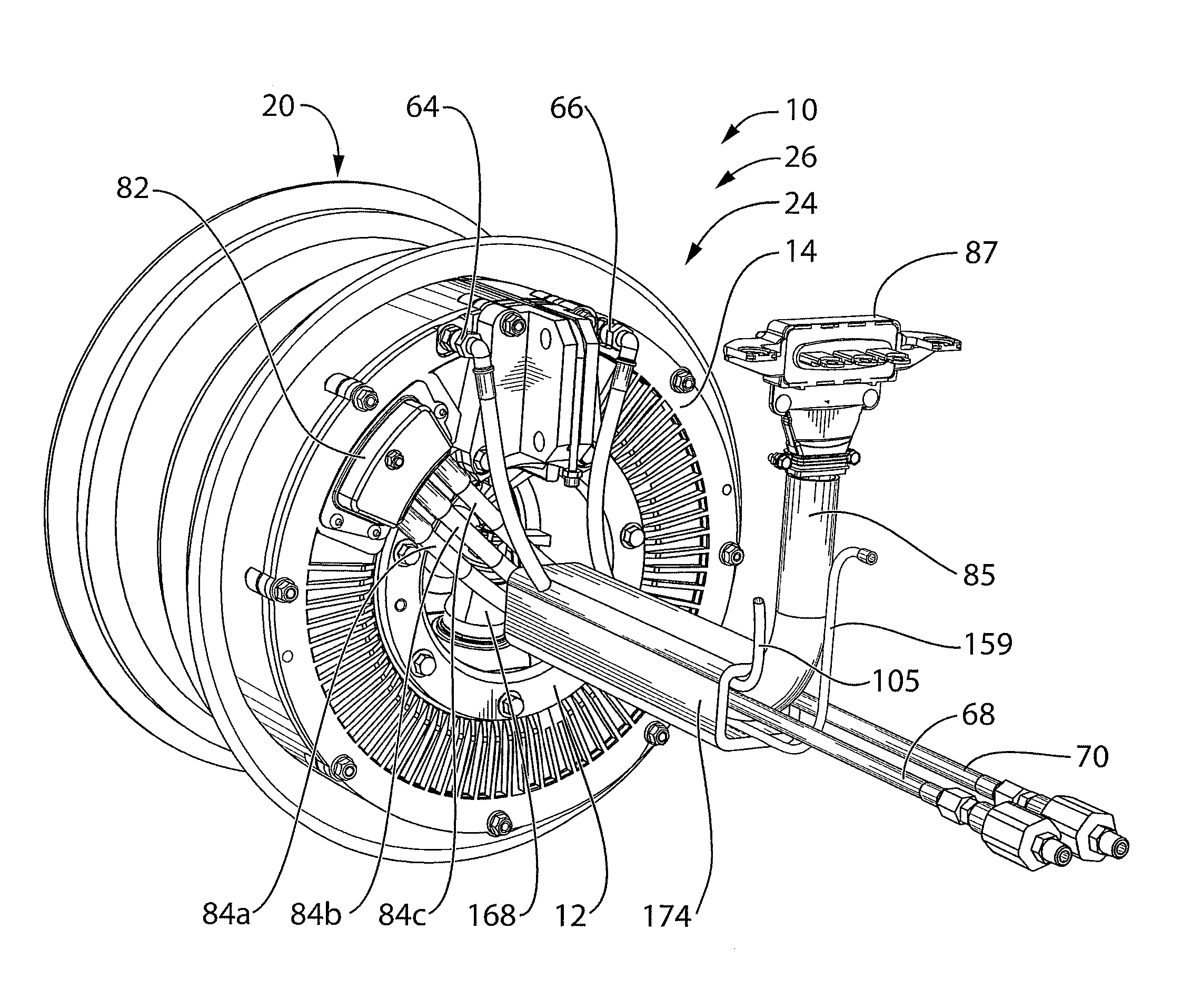
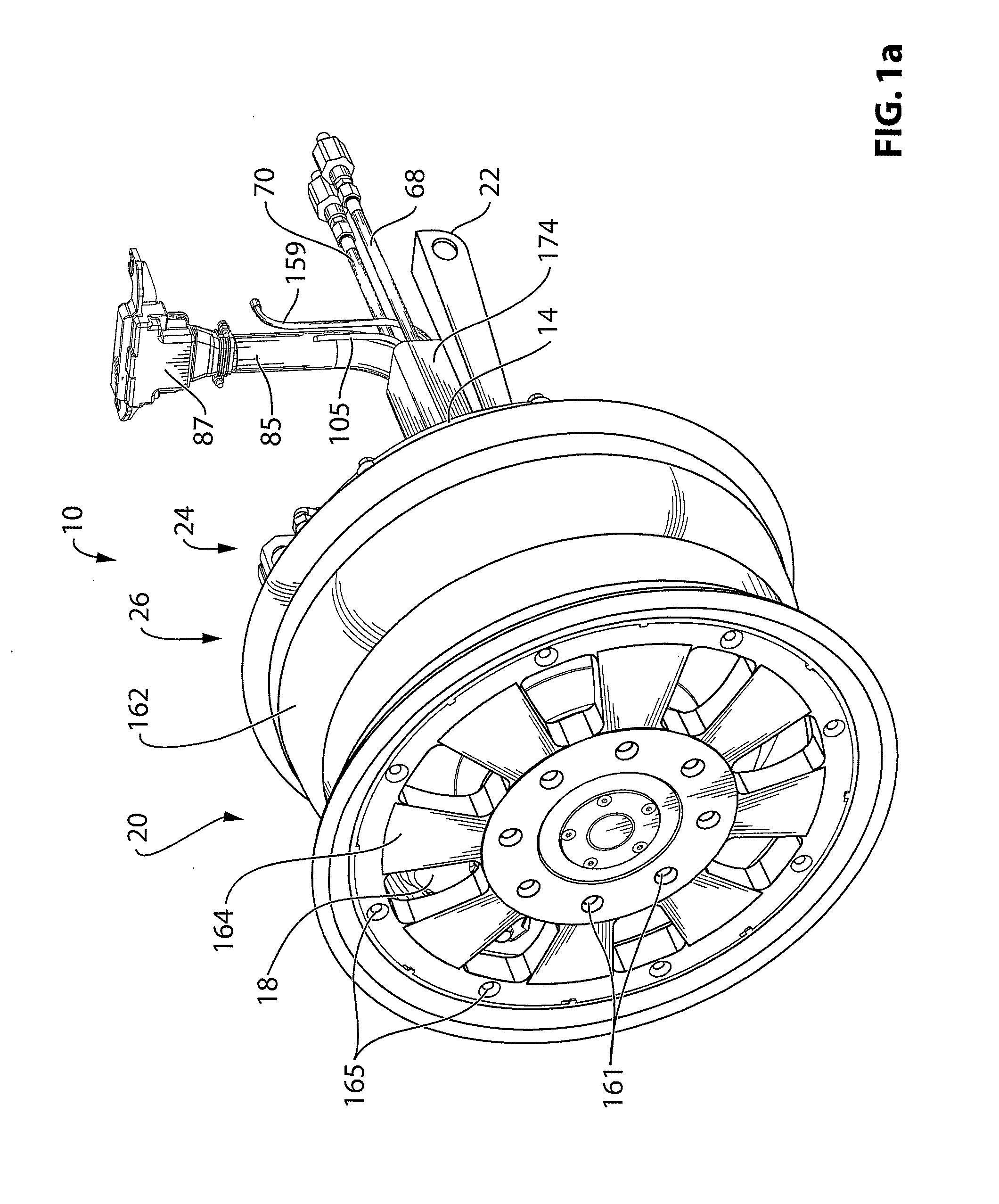
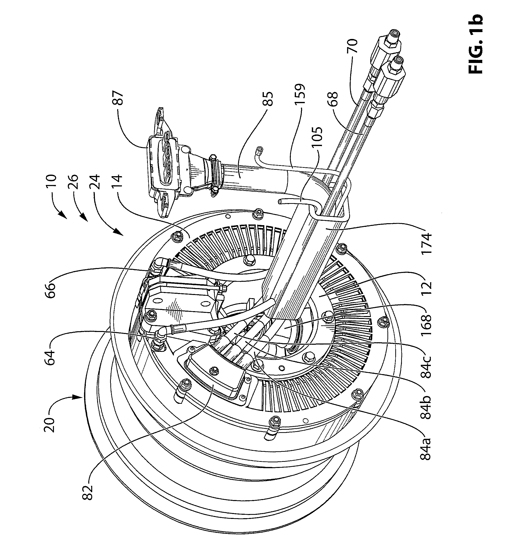
[0043]Reference is made to FIG. 1a, which shows a corner assembly 10 for a vehicle (not shown). The corner assembly 10 may be suitable for several types of electrically powered vehicles. For example, embodiments of the corner assembly 10 may be suitable for vehicles that are used on-road (eg. passenger cars), vehicles that will be used off-road (eg. sport-utility vehicles), civilian vehicles, military vehicles, high speed vehicles (eg. sports cars), high-torque vehicles,

[0044]As more clearly shown in FIG. 1b, the corner assembly 10 includes a drive assembly 24, a wheel 20, a brake 18 and a suspension member, (specifically a lower control arm 22). Referring to FIG. 2, the drive assembly 24 includes a non-rotating support member 12, an electric motor 14 and a gearbox 16. The drive assembly 24, the brake 18 and the wheel 20 may together be referred to as a wheel assembly 26.

[0045]The non-rotating support member 12 has a non-rotating support member axis Asm associated therewith. The non...


PUM


Abstract

In a first aspect, the invention is directed to a wheel assembly for a vehicle, including a non-rotating support member, a wheel and an electric motor. Loads incurred during vehicle use can cause dynamic flexing of portions of the wheel. The wheel assembly in accordance with the first aspect of the invention has a load path for loads incurred by the wheel that passes from the wheel to the non-rotating support member without passing through the motor, thereby reducing a potential source of distortion of the gap in the motor (between the motor's rotor and stator) during the aforementioned flexing.

Description

FIELD OF THE INVENTION[0001]The present invention relates to electric vehicles (ie. vehicles that are powered at least partly by an electric motor) and more particularly to electric vehicles with drive motors that are positioned at one or more wheels.BACKGROUND OF THE INVENTION[0002]Electric vehicles offer the promise of powered transportation through the use of electric motors while producing few or no emissions. Some electric vehicles are powered by electric motors only and rely solely on the energy stored in an on-board battery pack. Other electric vehicles are hybrids, and include an internal combustion engine, which may, for example, be used to assist the electric motor in driving the wheels (a parallel hybrid), or which may, for example, be used solely to charge the on-board battery pack, thereby extending the operating range of the vehicle (a series hybrid). Yet other electric vehicles are in the form of fuel cell vehicles, which use on-board fuel cells to produce electrical ...

Claims


Application Information

Patent Timeline
IPC IPC(8): B60K7/00B23P11/00B60K1/00
CPCB60K7/0007B60K17/043Y10T29/49616B60K2007/0038B60K2007/0092B60K17/046
Inventor WEBER, JAMES L.LI, ZHESHENGKENDALL, TODD A.
Owner WEBER JAMES L
Why Eureka
Try Eureka