
Anesthesia tube assembly

a technology of anesthesia tube and assembly, which is applied in the direction of breathing mask, breathing protection, other medical devices, etc., can solve the problems of reapplication of tape, necrosis of cartilage at the tip of the nose, and inability to secure the tube to the patien

Inactive Publication Date: 2010-12-02
HAJARIAN HAMID CYRUS +1
View PDF6 Cites 6 Cited by
  • Summary
  • Abstract
  • Description
  • Claims
  • Application Information

AI Technical Summary

Problems solved by technology

This pressure can create necrosis of the cartilage at tip of the nose.
This approach does not provide a secure attachment of the tube to the patient.
The removal and reapplication of tape can be a time consuming process, which increases the time required to perform a procedure.

Method used


Image

  • Anesthesia tube assembly
  • Anesthesia tube assembly
  • Anesthesia tube assembly

Examples


Embodiment Construction

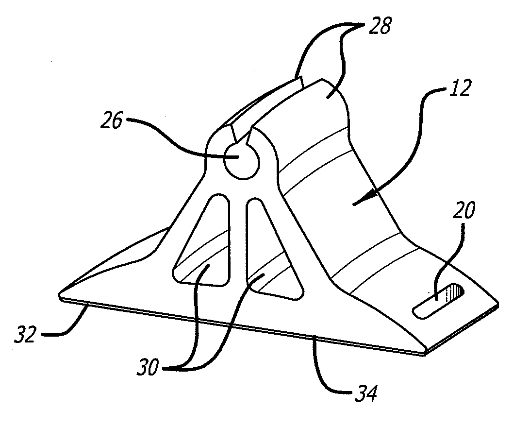
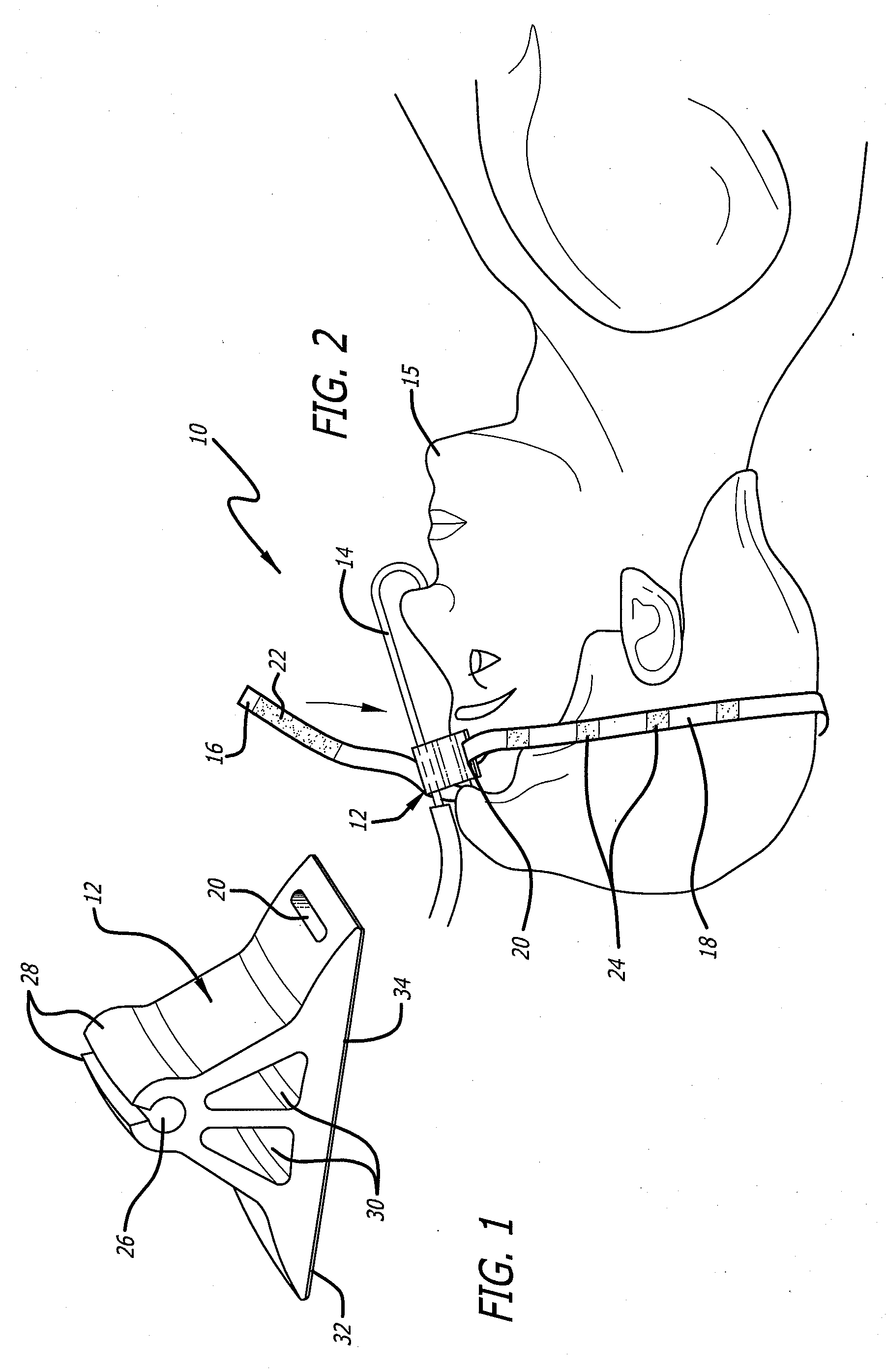
[0014]Disclosed is an anesthesia tube assembly with a fixture that can secure an anesthesia tube to a patient. The fixture can be secured to a patient with a strap. The tube can be inserted into a channel of the fixture. The assembly does not require gauze or tape that is used in prior art methods for securing the tube.

[0015]Referring to the drawings more particularly by reference numbers, FIGS. 1 and 2 show an embodiment of an anesthesia tube assembly 10. The assembly 10 includes a fixture 12 that secures an anesthesia tube 14 to a patient 15. The fixture 12 can be secured in place by a strap 18.

[0016]One end of the strap 18 can be attached to the fixture 12 at opening 20. The other end of the strap 18 may have hook or loop material 22 that attaches to corresponding loop or hook material 24 on the top of the strap. The strap 18 may be constructed from an elastic material to create a tension force when the fixture 12 is secured to the patient 15. Although hook and loop material is d...


PUM


Abstract

An anesthesia tube assembly with a fixture that can secure an anesthesia tube to a patient. The fixture can be secured to a patient with a strap. The tube can be inserted into a channel of the fixture.

Description

BACKGROUND OF THE INVENTION[0001]1. Field of the Invention[0002]The present invention relates to a fixture that secures an anesthesia tube to a patient.[0003]2. Prior Art[0004]Patients under general anesthesia for maxillofacial surgery must be nasally intubated. The tube will go through the nose and into the patient's trachea. The portion of the tube outside of the patient' nose has a 180 degree turn that extends to the patient's forehead. The anesthesia tube must be securely attached to the patient's head to prevent unwanted tube movement. Unwanted movement of the anesthesia tube can create pressure on the nose. This pressure can create necrosis of the cartilage at tip of the nose.[0005]To prevent unwanted movements, the tube is typically secured to the patient's head with gauze and tape. The tape is typically applied to a head drape placed on the patient's head. This approach does not provide a secure attachment of the tube to the patient. Additionally, if there is a desire to mov...

Claims


Application Information

Patent Timeline
Patent Type & Authority Applications(United States)
IPC IPC(8): A62B7/00
CPCA61M16/01A61M2209/088A61M16/0497A61M16/0488
Inventor HAJARIAN, HAMID CYRUSGHODOUSSI, MODJTABA
Owner HAJARIAN HAMID CYRUS
Learn More