Metal-to-metal seal with travel seal bands

a technology of metal-to-metal seals and sealing bands, which is applied in the direction of sealing/packing, mechanical equipment, borehole/well accessories, etc., and can solve problems such as leakage, leakage of seals on the side, and leakage of seals

Inactive Publication Date: 2010-12-02
VETCO GRAY
View PDF15 Cites 52 Cited by
  • Summary
  • Abstract
  • Description
  • Claims
  • Application Information

AI Technical Summary

Benefits of technology

[0009]In the illustrated embodiments, a radial gap exists between the outer wall of the seal and the inner wall of the mating housing. Such gap is required for installation in the field and is sufficiently large to require plastic deformation of the seal body, but not the energizer ring. In order to accommodate sealing over scratches and surface trauma of the wellhead members, soft metallic inlays form a band around the exterior surfaces of the seal inner and outer walls. The inlays have grooves formed on the sealing side of the inlay and are preferably in a V configuration to assist in the flow of inlay material to provide a seal. The size and thickness of the metallic inlays are sufficient to provide for scratch filling and therefore sealing between the mating members.
[0012]The combination of stored energy provided for by the energizing rings, the locking mechanisms of the seal ring and the energizing ring, the slick areas interrupting the wicker profiles, and the compliant soft outer inlays, provides gas tight sealing under extreme thermal conditions. Alternatively, the soft inlays may be made from a non-metallic material or polymer such as PEEK (poly-ether-ether-keytone) or PPS (polyphenylene sulfide).

Problems solved by technology

A reduction in axial force on the energizing ring results in a reduction in the radial inward and outward forces on the inner and outer walls of the seal ring, which may cause the seal to leak.
A loss of radial loading between the seal and its mating surfaces due to thermal transients may also cause the seal to leak.
However, with travel of the seal due to thermal and pressure effects, the seal can experience a moment that leads to leakage on the side with the slick bore.
However, seal travel due to thermal growth cycles and continued increases in production pressure still resulted in seal leakage.

Method used


Image

  • Metal-to-metal seal with travel seal bands
  • Metal-to-metal seal with travel seal bands
  • Metal-to-metal seal with travel seal bands

Examples


Embodiment Construction

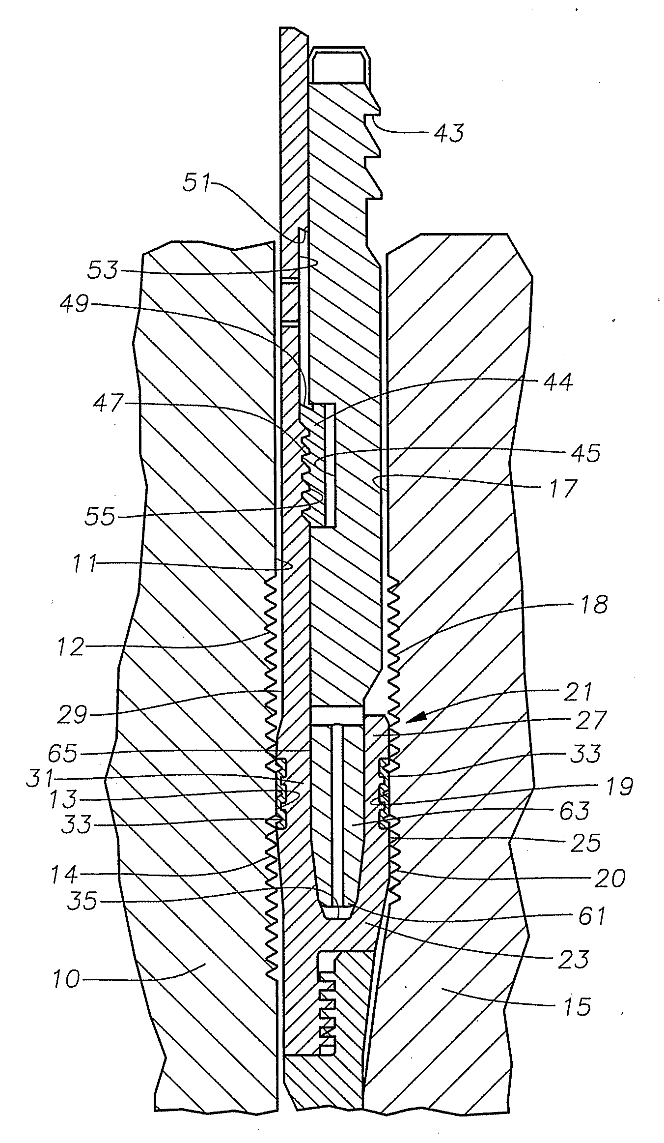
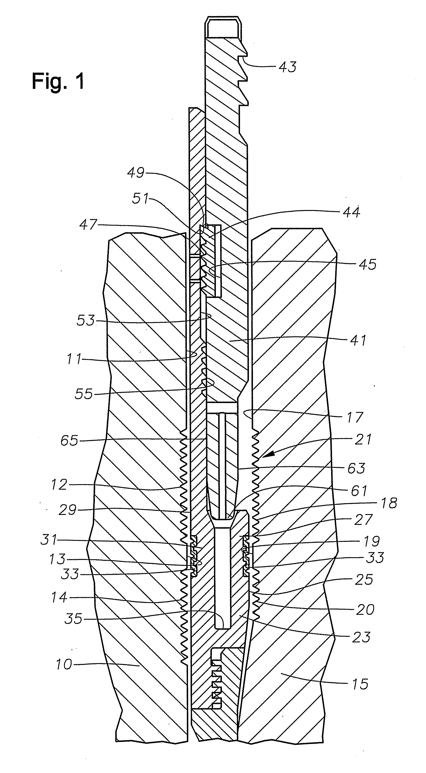
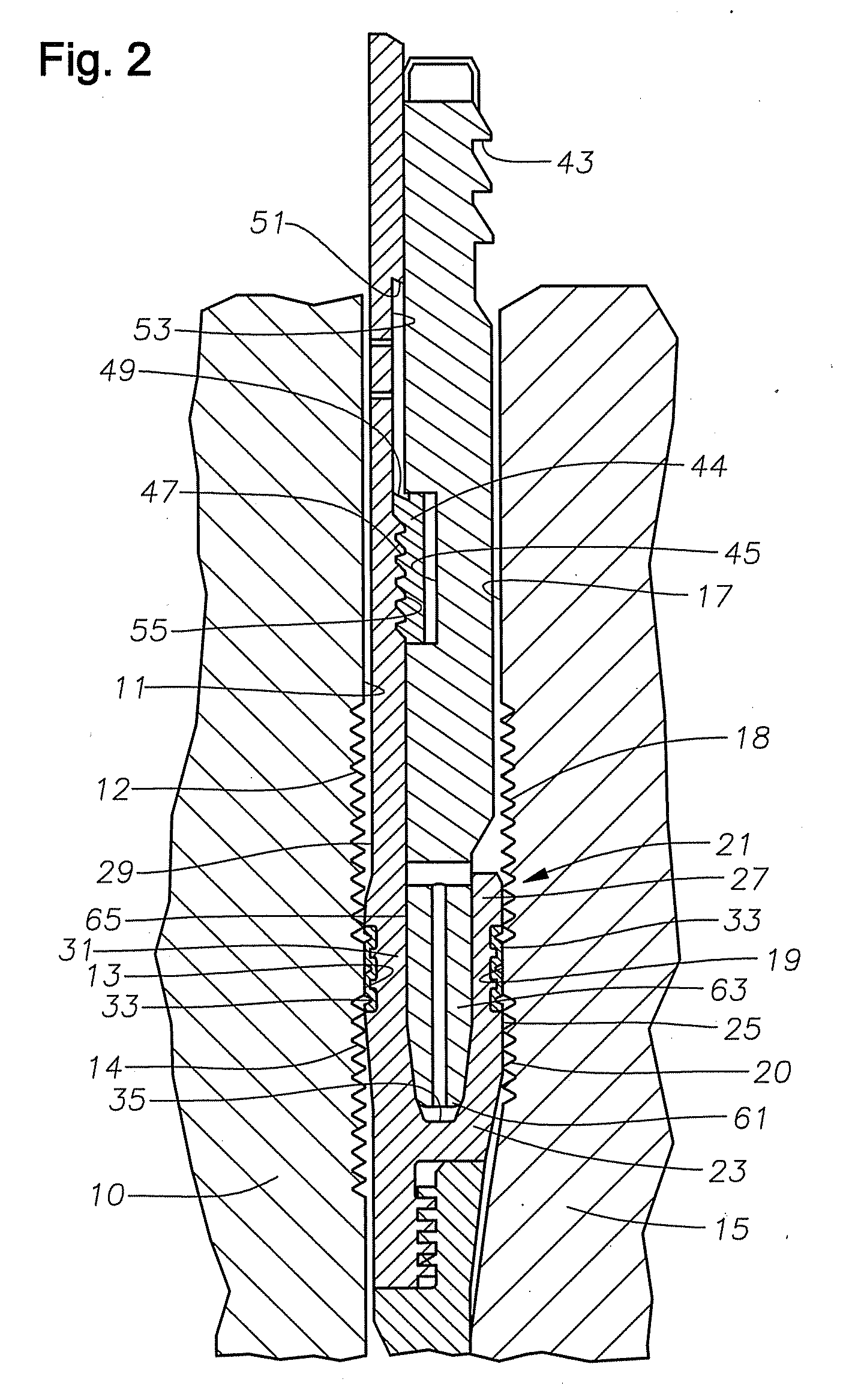
[0015]Referring to FIG. 1, an embodiment of the invention shows a portion of a high pressure wellhead housing 10. Housing 10 is located at an upper end of a well and serves as an outer wellhead member in this example. Housing 10 has a bore 11 located therein.

[0016]In this example, the inner wellhead member comprises a casing hanger 15, which is shown partially in FIG. 1 within bore 11. Alternately, wellhead housing 10 could be a tubing spool or a Christmas tree and casing hanger 15 could instead be a tubing hanger, plug, safety valve, or other device. Casing hanger 15 has an exterior annular recess radially spaced inward from bore 11 to define a seal pocket 17. Wickers 12 and a slick area 13 are located on the wellhead bore 11 and wickers 18 and a slick area 19 are located on the cylindrical wall of seal pocket 17. In this example, the profiles of each set of wickers 12, 18 are interrupted by the slick areas 13, 19 such that wickers 12, 18 are located above and below the slick areas...


PUM


Abstract

A wellhead seal assembly that forms a metal-to-metal seal between inner and outer wellhead members. A metal seal ring has inner and outer walls separated by a slot. The exterior surfaces of the outer and inner walls contain a soft metal inlay. A wicker profile with a slick area is located on the outer surface of the inner wellhead member and on the inner surface of the outer wellhead member. An energizing ring is moved into the slot to force the outer and inner walls of the seal into sealing engagement with the inner and outer wellhead members. The soft metal inlays deform onto the slick area on the wellhead members. The wickers on the wellhead members embed into the walls of the seal ring.

Description

FIELD OF THE INVENTION [0001]This invention relates in general to wellhead assemblies and in particular to a seal for sealing between inner and outer wellhead members.BACKGROUND OF THE INVENTION [0002]Seals are used between inner and outer wellhead tubular members to contain internal well pressure. The inner wellhead member may be a casing hanger located in a wellhead housing and that supports a string of casing extending into the well. A seal or packoff seals between the casing hanger and the wellhead housing. Alternatively, the inner wellhead member could be a tubing hanger that supports a string of tubing extending into the well for the flow of production fluid. The tubing hanger lands in an outer wellhead member, which may be a wellhead housing, a Christmas tree, or a tubing head. A packoff or seal seals between the tubing hanger and the outer wellhead member.[0003]A variety of seals of this nature have been employed in the prior art. Prior art seals include elastomeric and part...

Claims


Application Information

Patent Timeline
Patent Type & Authority Applications(United States)
IPC IPC(8): E21B33/03F16J15/08
CPCE21B33/04
Inventor NELSON, JOHN E.
Owner VETCO GRAY
Why Eureka
Try Eureka