
Variable Angle Locked Bone Plate

a locking plate and variable angle technology, applied in the field of locking bone fixation assembly, can solve the problems of cumbersome manipulation and tedious manipulation of multi-component traditional plate assembly

Inactive Publication Date: 2010-12-09
SYNTHES GMBH
View PDF16 Cites 111 Cited by
  • Summary
  • Abstract
  • Description
  • Claims
  • Application Information

AI Technical Summary

Problems solved by technology

These multi-component traditional plate assemblies can be cumbersome and tedious to manipulate during surgery to achieve the most desirable angle for directing the bone screw into the patient.

Method used


Image

  • Variable Angle Locked Bone Plate
  • Variable Angle Locked Bone Plate
  • Variable Angle Locked Bone Plate

Examples


Embodiment Construction

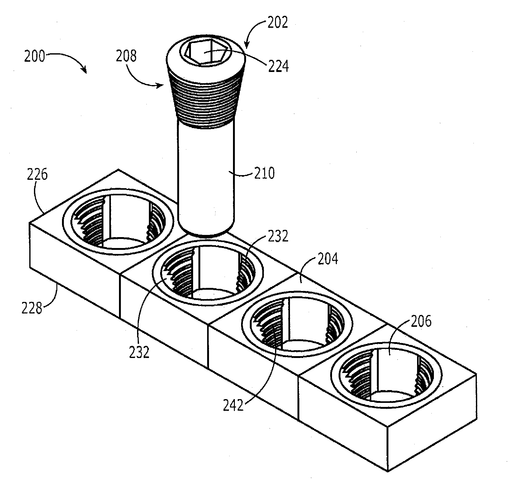
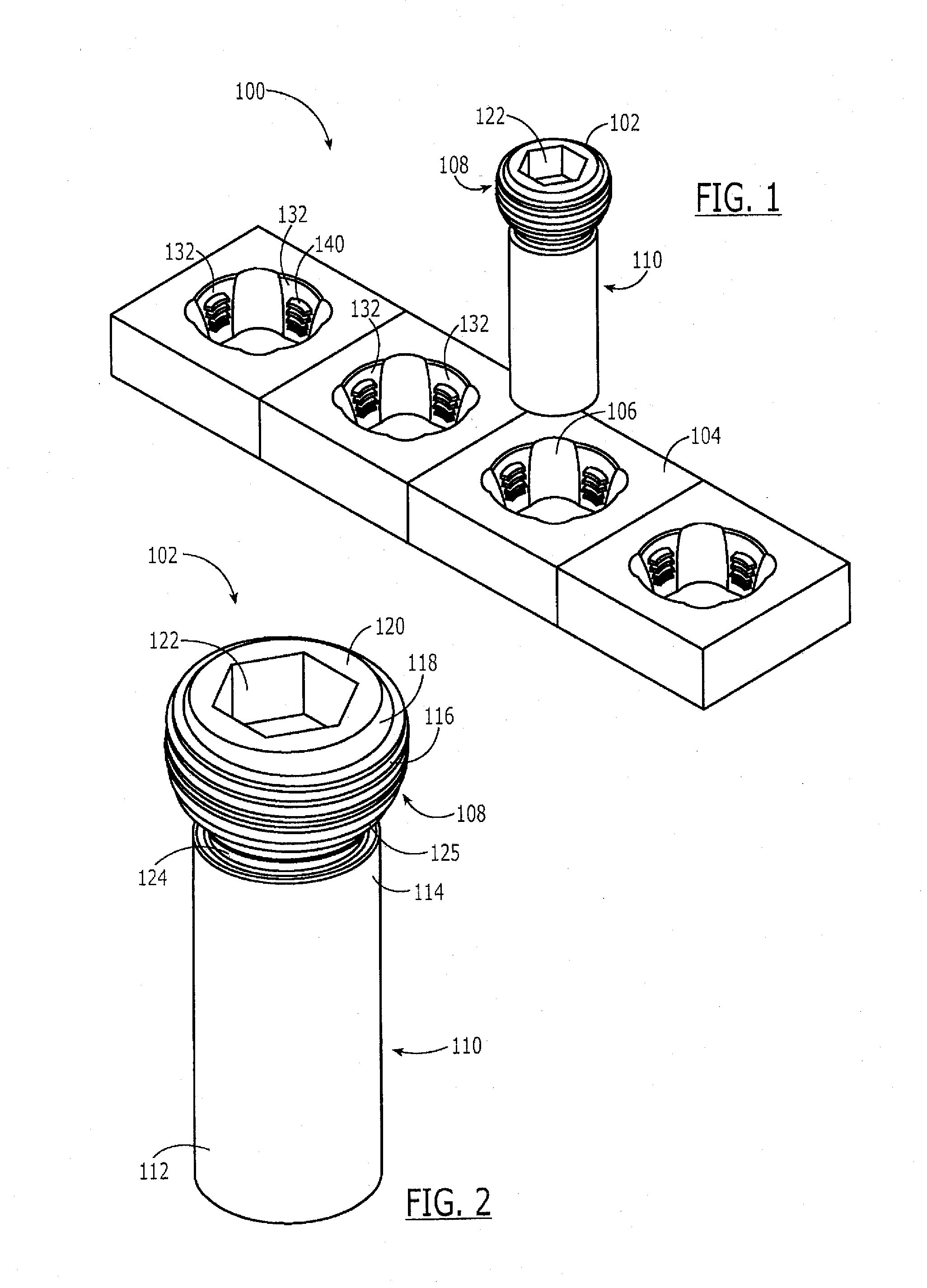
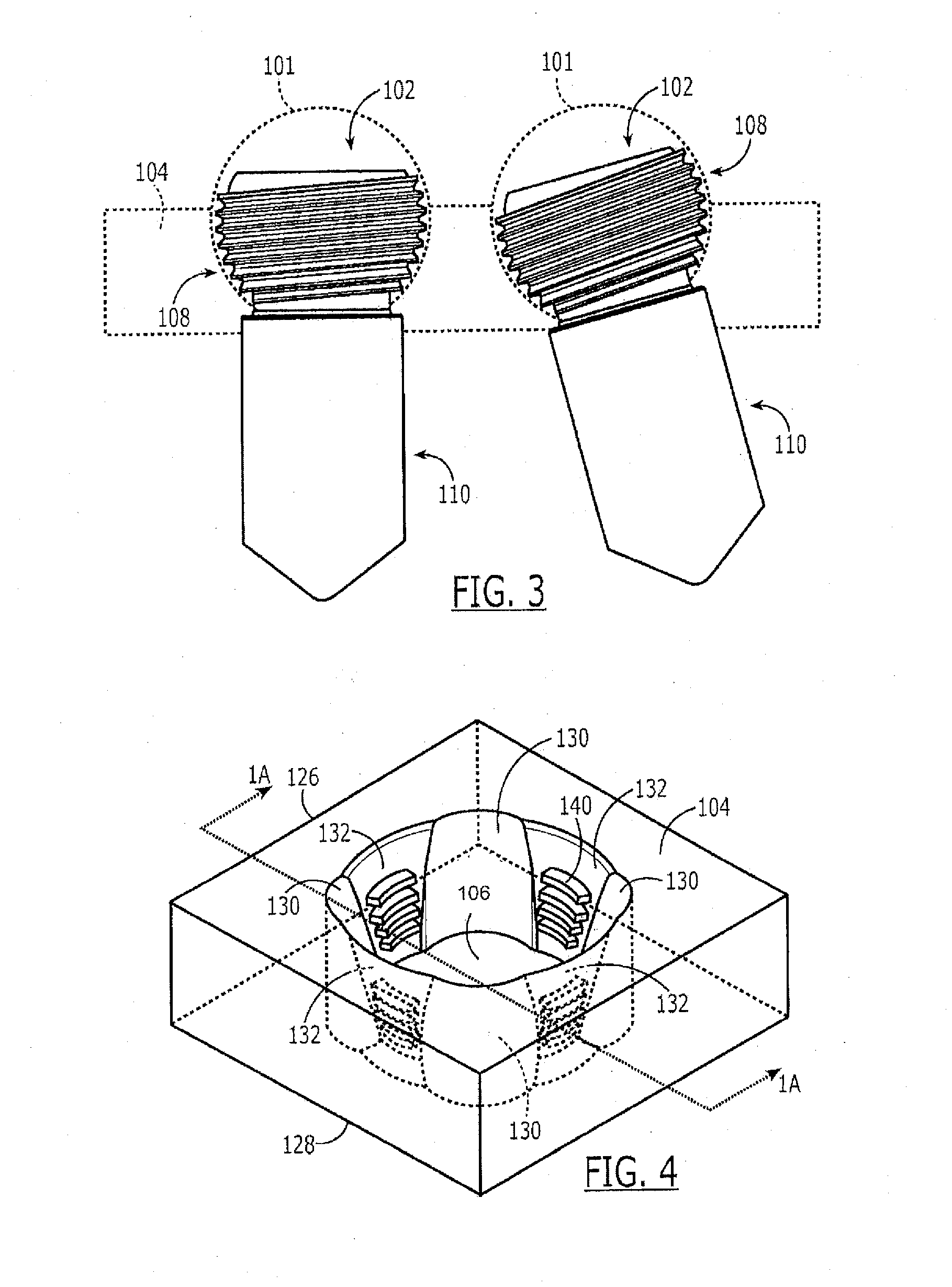
[0028]The present invention, which may be further understood with reference to the following description and the appended drawings, relates to devices for treating fractures and, in particular, to internal fixation devices for treating fractures. Exemplary embodiments of the present invention describe an improved bone fixation assembly that allows a surgeon to select an angle of a bone screw relative to a plate in a single action. The assembly uses only two components so that no rings, bushings or expansion head screws are needed. It will be understood by those of skill in the art that although the exemplary embodiments are described in regard to a screw / pin and a plate, the device may fix a fracture using any known fixation element.

[0029]As shown in FIGS. 1-10, a device 100 according to a first exemplary embodiment of the invention comprises a screw or pin 102 and a plate 104. As shown in FIG. 1, the plate 104 includes at least one opening 106 receiving the screw or pin 102. As sho...


PUM


Abstract

A plate for fixation to a target portion of bone to be treated, comprises a first fixation element receiving opening extending therethrough from a proximal surface to a distal surface, the first fixation element receiving opening including a plurality of columns distributed about a circumference thereof and a plurality of radially expanded sections separating adjacent ones of the columns from one another in combination with a plurality of projections formed on the columns, the projections extending from surfaces of the columns, shapes of the surfaces of the columns on which the projections are formed being selected so that, when engaged by a head of a bone fixation element, the projections engage a thread of a head of the bone fixation element to lock the bone fixation element in the first fixation element receiving opening at any user selected angle within a permitted range of angulation.

Description

PRIORITY CLAIM[0001]This application claims priority to (1) U.S. Provisional Application Ser. No. 61 / 000,907 entitled “Variable Angle Locked Bone Plate,” filed on Oct. 30, 2007 and (2) U.S. Provisional Application. Ser. No. 61 / 084,281, entitled “Variable Angle Locked Bone Plate,” filed on Jul. 29, 2008. The Specifications of the above-identified applications are incorporated herewith by reference.BACKGROUND[0002]The present invention is directed to a locked bone fixation assembly, and in particular to an assembly that allows for a surgeon-selected angle of the bone screw relative to the fixation device.[0003]Orthopedic fixation devices, both internal and external, are frequently coupled to bone using fasteners such as screws, threaded bolts or pins. For example, bone plates may be secured to bone with bone screws, inserted through plate holes. Securing the screws to the plate provides a fixed angle relationship between the plate and screw and reduces incidences of loosening. One met...

Claims


Application Information

Patent Timeline
IPC IPC(8): A61B17/80
CPCA61B17/8605A61B17/8057
Inventor DELL'OCA, ALBERTO A. FERNANDEZ
Owner SYNTHES GMBH
Learn More