

Dynamic fixation assemblies with inner core and outer coil-like member
a technology of dynamic fixation and inner core, which is applied in the direction of ligaments, surgery, medical science, etc., can solve the problems of reducing or eliminating the ability of spinal joints to move in a more normal relation to one another, affecting the normal movement of spinal joints, and having undesirable side effects. , to achieve the effect of reducing volume, low profile and convenient us
- Summary
- Abstract
- Description
- Claims
- Application Information
AI Technical Summary
Benefits of technology
Problems solved by technology
Method used
Image

Examples
second embodiment
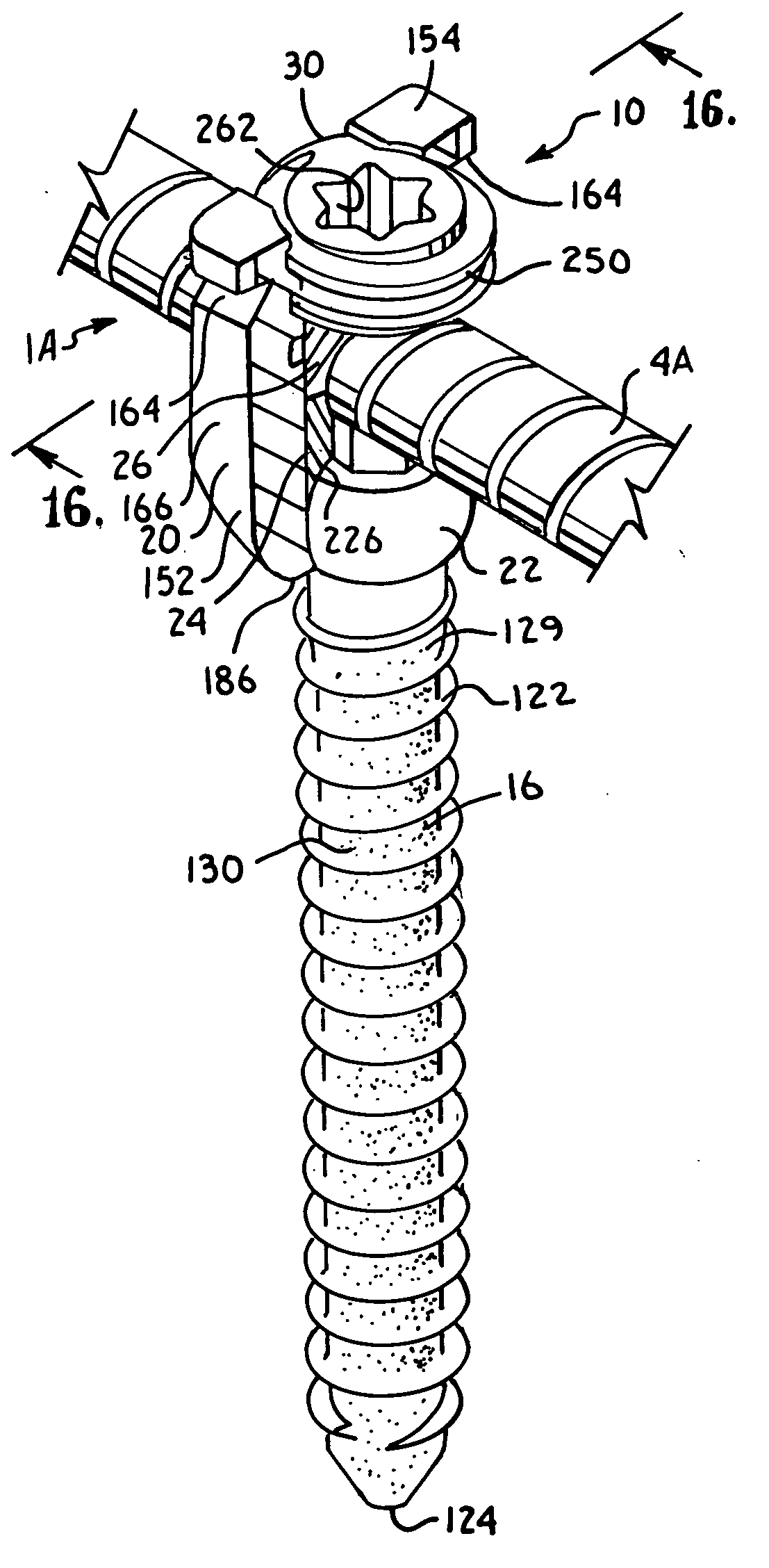
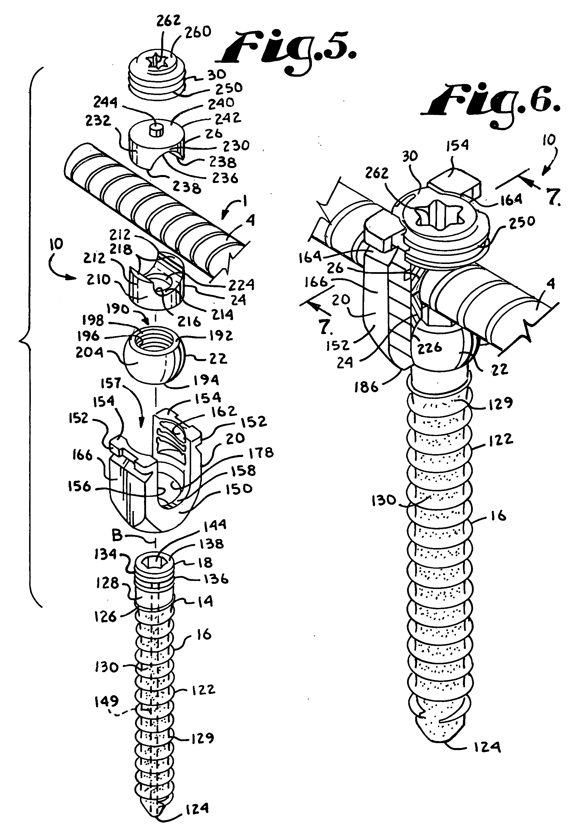
[0098]With reference to FIGS. 10-13, the reference numeral 1A generally designates a non-fusion dynamic stabilization longitudinal connecting member assembly according to the present invention. The connecting member assembly 1A includes an outer, cannulated coil-like connecting member 4A and a substantially cylindrical core or insert 8A, having an outer helical thread 9A, the core being threadably receivable in the coil-like member 4A and fixed thereto at only one end of the core 8A as will be described more fully below. The dynamic connecting member assembly 1A cooperates with at least a pair of polyaxial bone screw assemblies according to the invention, one of such assemblies, generally 10, shown in FIGS. 14-17 and previously described herein with reference to FIGS. 5-9. The closure structure 30 also shown in FIGS. 14-17 and previously described herein with respect to FIGS. 5-7, also cooperates with the connecting member 1A and the bone screw assembly 10 in the manner previously d...
fifth embodiment
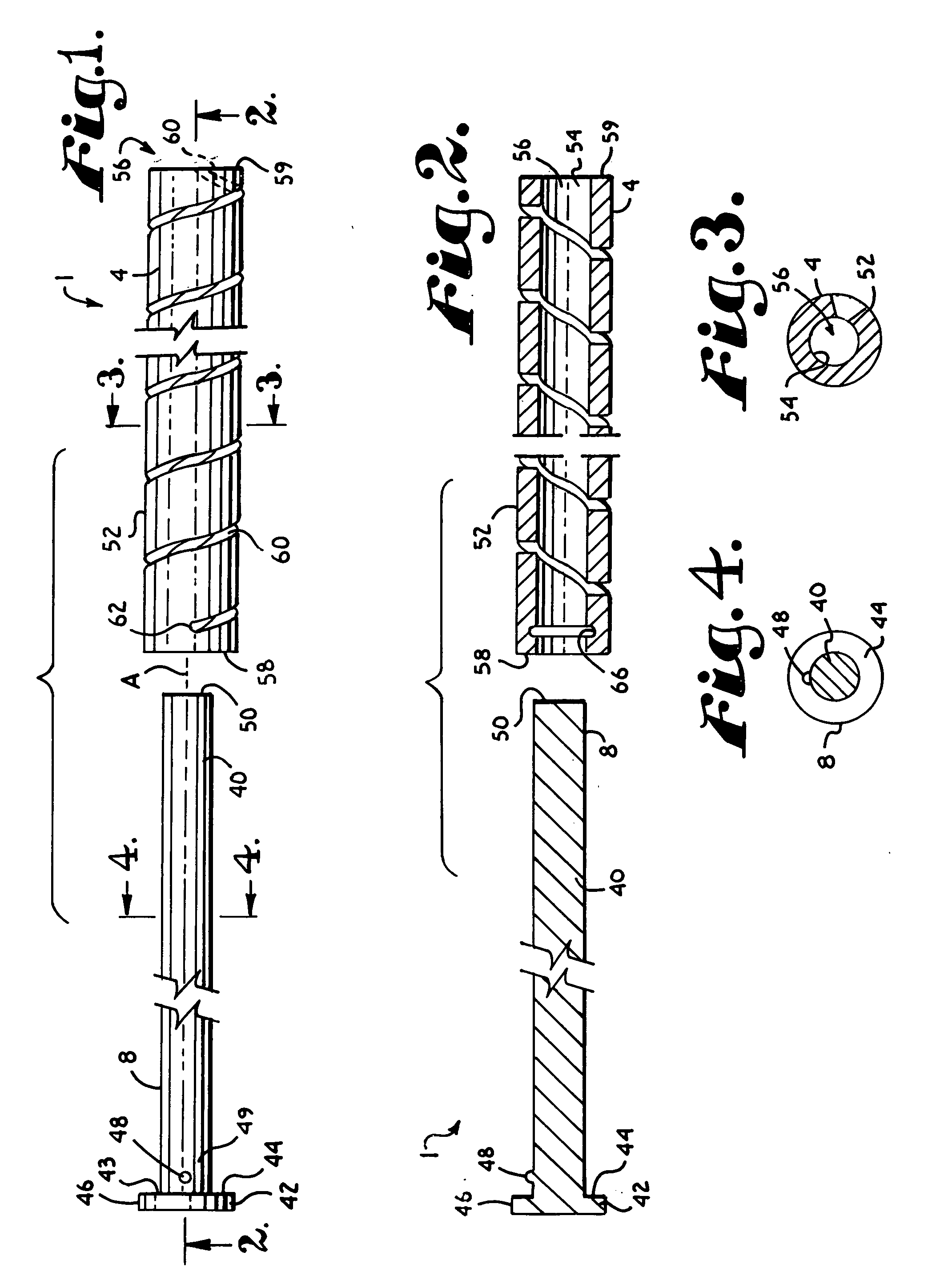
[0165]With reference to FIGS. 40-42, a dynamic longitudinal connecting member assembly according to the invention, generally 1C, is substantially identical to the assembly 1 illustrated in FIGS. 1-4, with the exception that the stop 42 is replaced by a connecting member having a solid outer surface illustrated by a rod 42C. In particular, the assembly 1C includes an outer coil-like member 4C and an inner solid cylindrical core 8C identical or substantially similar to the respective coil-like member 4 and the inner core 8 of the connecting member assembly 1 previously described herein. Therefore details of the coil-like member 4C and the inner core 8C will not be repeated here.
[0166]The inner core 8C is fixed or integral with a longitudinal connecting member extension or solid rod 42C. The rod 42C is integral or fixedly attached to the inner core 8C at a first end 43C thereof. The rod 42C is substantially coaxial with the inner core 8C and may be of any desired length, measured from ...
sixth embodiment
[0168]With reference to FIG. 43, a dynamic longitudinal connecting member assembly according to the invention, generally 1D, is substantially identical to the assembly 1A illustrated in FIGS. 10-13, with the exception that the stop 42A has been replaced by a solid connecting member or rod 42D. In particular, the assembly 1D includes an outer coil-like member 4D and an inner solid cylindrical core 8D having a helical thread 9D identical or substantially similar to the respective coil-like member 4A, the inner core 8A and the thread 9A of the connecting member assembly 1A previously described herein. Therefore details of the coil-like member 4D and the inner threaded core 8D will not be repeated here. Again, the connecting members could be curvilinear.
[0169]The inner core 8D is fixed or integral with a longitudinal connecting member extension illustrated as a solid rod 42D. The rod 42D is attached to the inner core 8D at a first end 43D thereof. In the embodiment shown, the rod 42D is...
PUM
 Abstract
Description
Claims
Application Information