Method and System for Calculating and Reporting Slump in Delivery Vehicles

a technology for calculating and reporting the slump of delivery vehicles, applied in the field of delivery vehicles, can solve the problems of unscientific adjustment, difficult to solve problems, and customers cannot be charged an extra amoun

Inactive Publication Date: 2010-12-09
VERIFI INC
View PDF91 Cites 27 Cited by
  • Summary
  • Abstract
  • Description
  • Claims
  • Application Information

AI Technical Summary

Problems solved by technology

The adjustment is often unscientific—the driver add water from any available water supply (sometimes there is water on the truck) by feeding a hose directly into the mixing barrel and guessing as to the water required.
However, if excess water is added, causing the mix to fail the slump test, the problem is more difficult to solve, because it is then necessary for the concrete mixing truck to return to the depot in order to add extra particulate concrete ingredients to correct the problem.
In addition, if excess liquid component has been added, the customer cannot be charged an extra amount for return of the concrete mixing track to the central depot for adding additional particulate concrete ingredients to correct the problem.
This, in turn, means that the concrete supply company is not producing concrete economically.
Such a communications device is not compatible with status systems used in the concrete industry.
A further difficulty has arisen with the operation of concrete delivery vehicles in cold weather conditions.
Unfortunately this water supply is susceptible to freezing in cold weather, and / or the water lines of the concrete truck are susceptible to freezing.
The truck operator's duties should include monitoring the weather and ensuring that water supplies do not freeze; however, this is often not done and concrete trucks are damaged by frozen pipes, and / or are taken out of service to be thawed after freezing.

Method used


Image

  • Method and System for Calculating and Reporting Slump in Delivery Vehicles
  • Method and System for Calculating and Reporting Slump in Delivery Vehicles
  • Method and System for Calculating and Reporting Slump in Delivery Vehicles

Examples


Embodiment Construction

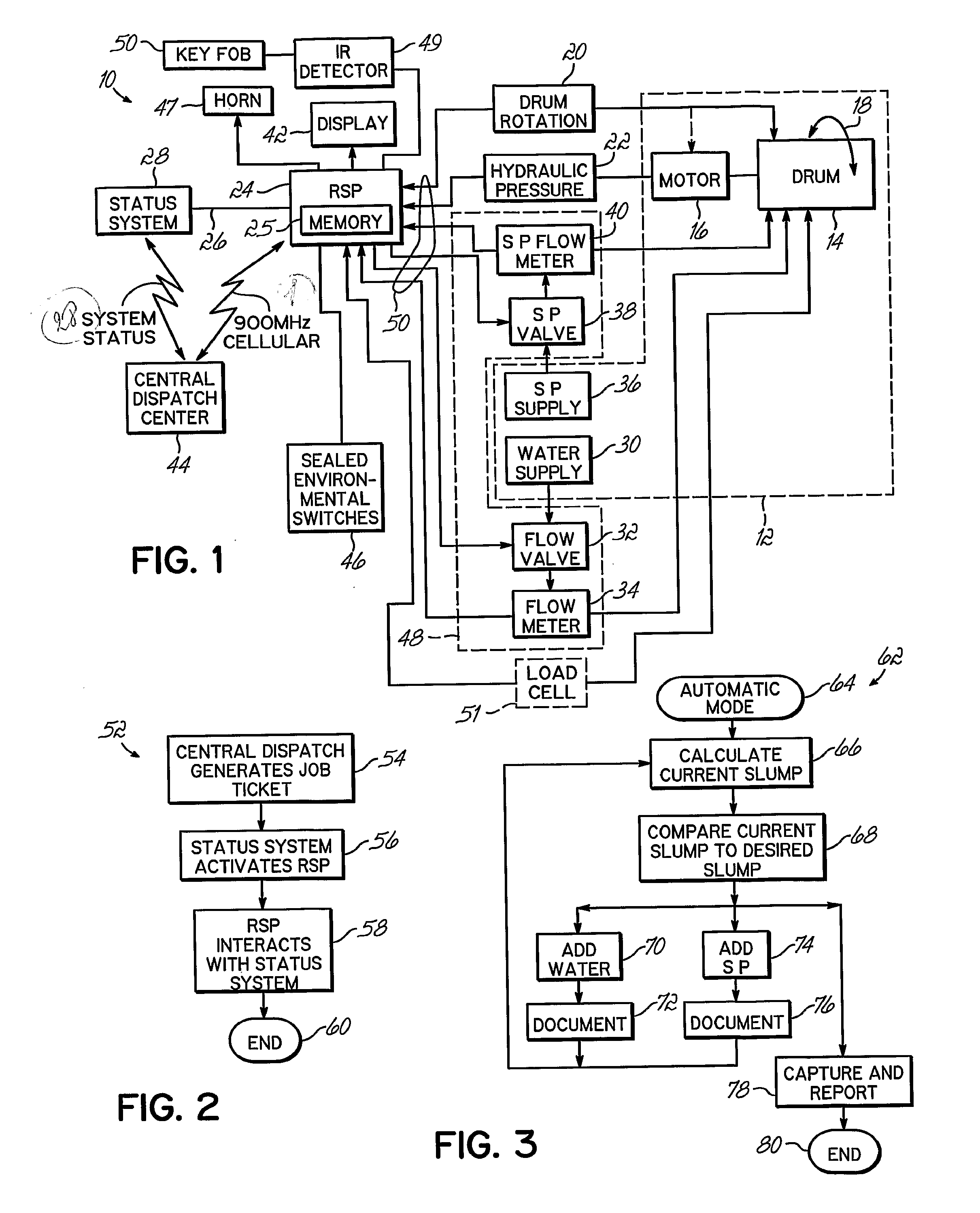
[0032]Referring to FIG. 1, a block diagram of a system 10 for calculating and reporting slump in a delivery vehicle 12 is illustrated. Delivery vehicle 12 includes a mixing drum 14 for mixing concrete having a slump and a motor or hydraulic drive 16 for rotating the mixing drum 14 in the charging and discharging directions, as indicated by double arrow 18. System 10 comprises a rotational sensor 20, which may be installed directly on or mounted to the mixing drum 14, or included in the motor driving the drum, and configured to sense the rotational speed and direction of the mixing drum 14. The rotational sensor may include a series of magnets mounted on the drum and positioned to interact with a magnetic sensor on the truck to create a pulse each time the magnet passes the magnetic sensor. Alternatively, the rotational sensor may be incorporated in the driving motor 16, as is the case in concrete trucks using Eaton 2000, 4000 and 6000 series hydraulic motors. In a third potential em...


PUM

PropertyMeasurementUnit
frequencyaaaaaaaaaa
widthaaaaaaaaaa
rotational speedaaaaaaaaaa

Abstract

A system for calculating and reporting slump in a delivery vehicle having a mixing drum 14 and hydraulic drive 16 for rotating the mixing drum, including a rotational sensor 20 configured to sense a rotational speed of the mixing drum, a hydraulic sensor 22 coupled to the hydraulic drive and configured to sense a hydraulic pressure required to turn the mixing drum, and a communications port 26 configured to communicate a slump calculation to a status system 28 commonly used in the concrete industry, wherein the sensing of the rotational speed of the mixing drum is used to qualify a calculation of current slump based on the hydraulic pressure required to turn the mixing drum.

Description

RELATED APPLICATIONS[0001]The application is a divisional of pending U.S. application Ser. No. 10 / 599,130, which was filed Sep. 20, 2006, which is a U.S. National Phase of PCT / US2005 / 004405 filed Feb. 14, 2005 which claims benefit of U.S. Provisional Application 60 / 554,720, filed Feb. 13, 2004, and is related to U.S. application Ser. No. 11 / 834,002, filed Aug. 5, 2007 and U.S. application Ser. No. 11 / 764,832, filed Jun. 19, 2007. All of the above-mentioned applications are hereby incorporated by reference.FIELD OF THE INVENTION[0002]The present invention generally relates to delivery vehicles and particularly to mobile concrete mixing trucks that mix and deliver concrete. More specifically, the present invention relates to the calculation and reporting of slump using sensors associated with a concrete truck.BACKGROUND OF THE INVENTION[0003]Hitherto it has been known to use mobile concrete mixing trucks to mix concrete and to deliver that concrete to a site where the concrete may be ...

Claims


Application Information

Patent Timeline
Patent Type & Authority Applications(United States)
IPC IPC(8): G06F19/00B28C5/42B28C7/02B28C7/12
CPCB28C5/422B28C7/12B28C7/026B28C7/022
Inventor COOLEY, ROYCOMPTON, JOHN I.TOPPUTO, MICHAEL
Owner VERIFI INC
Why Eureka
Try Eureka