
Radial flow filter with traveling spray device

a technology of radial flow and spray device, which is applied in the direction of cleaning process and apparatus, cleaning using liquid, and separation processes, etc. it can solve the problems of affecting so as to minimize the required pressure, maximize fluidizing effect, and accentuate the effect of spraying

Active Publication Date: 2011-01-06
MARTIN JOHN D
View PDF16 Cites 13 Cited by
  • Summary
  • Abstract
  • Description
  • Claims
  • Application Information

AI Technical Summary

Benefits of technology

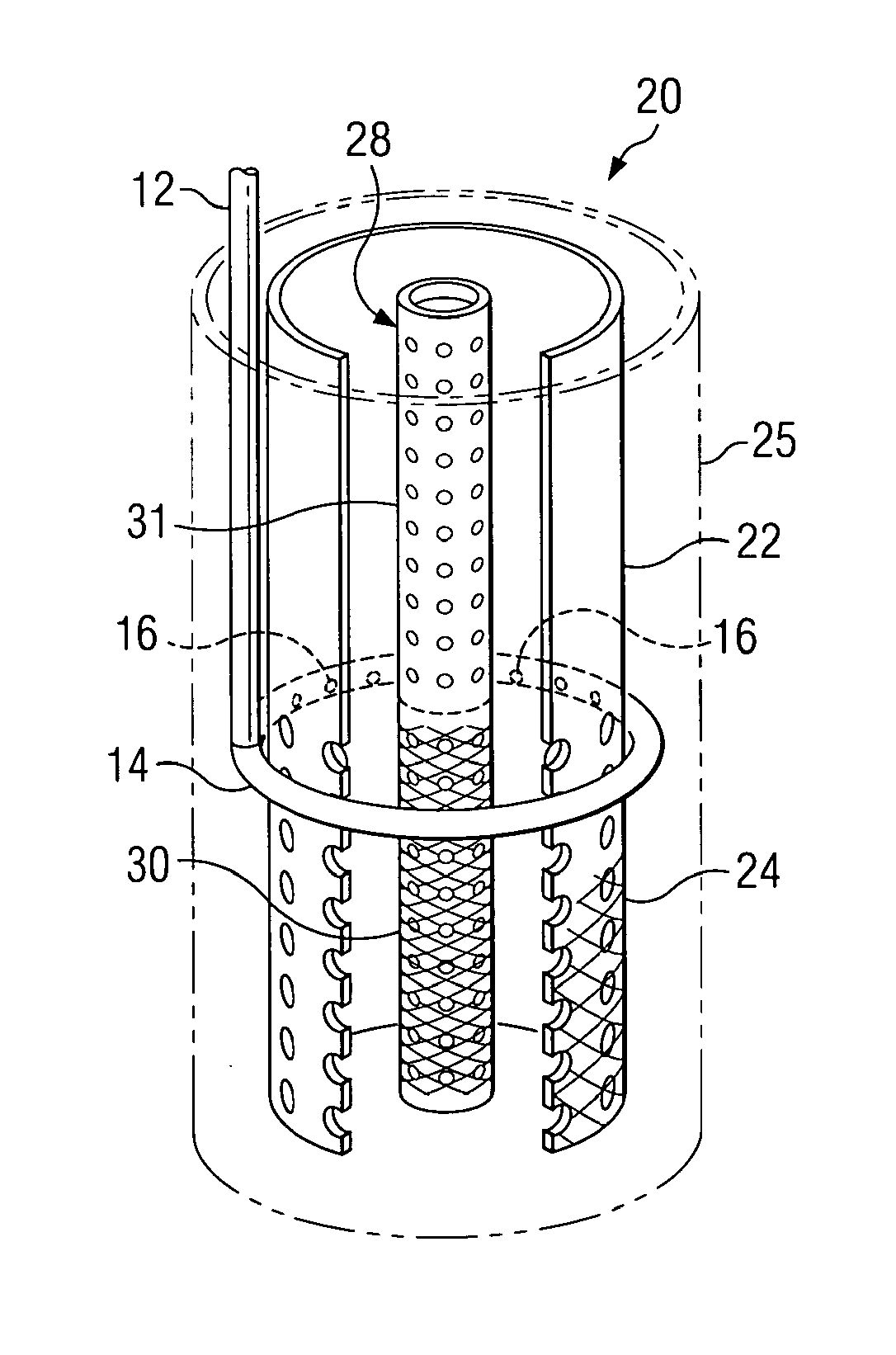
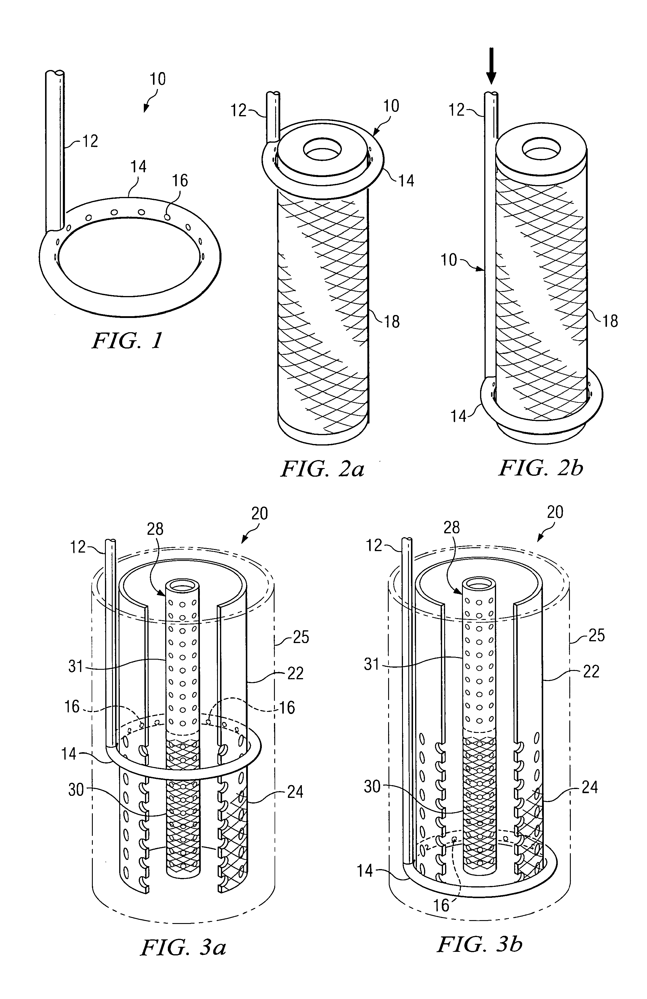
[0010]According to a preferred embodiment of the invention, a spray cycle is initiated when the filter material becomes clogged with contaminants. A pressurized fluid source is coupled to the spray device to produce a spraying effect, as well as to move the spray device along the surface of the filter. The spraying device is transported to those areas of the filter clogged by contaminants to release the same and restore the filter to its original condition.
[0013]The spray cleaning operation can be maximized by allowing the fluid and pressure in the filter to be removed before the spray cycle is initiated. This preconditioning of the filter minimizes the inertia of the medium through which the spray device is transported and also maximizes the impact of the spray stream on the surface to be cleaned.
[0017]In another embodiment of the invention, hydraulics can be utilized to maximize the spraying and fluidizing effect and minimize the required pressure.
[0018]In another embodiment of the invention, pressurized air can be used to accentuate the impact of the spraying and travel to facilitate removal of residue from a surface.

Problems solved by technology

The replacement of the filter elements is effective to restore the filter operation, but can be expensive and time consuming.
However, and most importantly, the retaining screens that contain the nonbonded media can also become plugged over time and need to be cleaned, as the fluidization process does not always clean the screens sufficiently.
An expensive alternative is to replace the retaining screens with new, clean retaining screens, although this is expensive and time consuming.
In the case of a filter employing a nonbonded filter medium, the filter medium itself can be regenerated by a fluidizing operation, but the buildup on either the outside or inside retaining screens can become clogged with residue which requires removal to restore the operation of the entire filter.

Method used


Image

  • Radial flow filter with traveling spray device
  • Radial flow filter with traveling spray device
  • Radial flow filter with traveling spray device

Examples


Embodiment Construction

[0035]Reference is made to U.S. Pat. No. 6,322,704 by Martin, the “Martin patent,” for a complete discussion of the structure and operation of a radial flow fluidizable filter employing a nonbonded media. The Martin patent is referenced to herein for its structure and adaptation to provide fluidization of a nonbonded media in a radial flow filter. The complete disclosure of the Martin patent is incorporated herein by reference thereto.

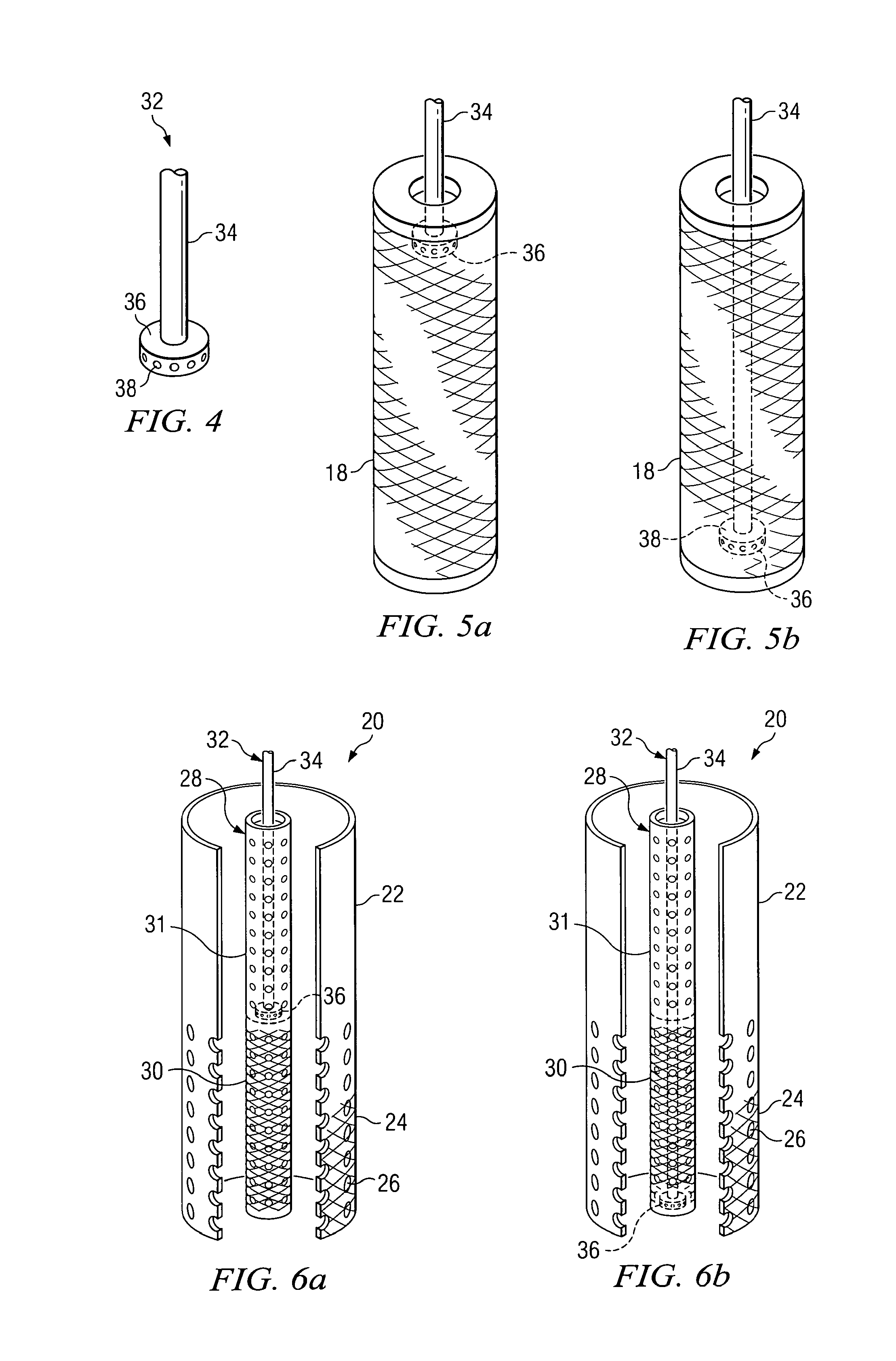
[0036]FIG. 1 illustrates in generalized form a traveling spray device 10 constructed in accordance with one embodiment of the invention. The device includes a spray halo 10 constructed with a tubular stem 12 connected to a spray member comprising an annular-shaped tubular halo 14. The tubular halo 14 is constructed with a number of nozzles 16 or orifices in a location so as to be directed generally radially inwardly. The pressurized liquid that is fed down the stem 12 flows into the tubular halo 14 and is thus jetted out of the nozzles 16. The pressuri...


PUM

PropertyMeasurementUnit
pressureaaaaaaaaaa
pressureaaaaaaaaaa
pressureaaaaaaaaaa

Abstract

A spray device for cleaning residue from a filter member. In one embodiment, the spray device includes a tubular stem telescopically slideable in a sleeve. A coil spring surrounds the stem and resists movement of the stem out of the sleeve. A tubular halo with nozzles is fastened to the end of the tubular stem so that when a pressurized fluid is applied to the stem, the stem is forced out of the sleeve against the spring force, thereby causing the halo to travel along a cylindrical filter surface. The pressurized fluid is also jetted from the nozzles and cleans the cylindrical surface. When the pressurized fluid is removed from the spray device, the spring retracts the stem and the halo back to a rest position. In another embodiment, the halo is replaced with a nozzle head that moves within a cylindrical filter surface to be cleaned.

Description

RELATED PATENT APPLICATION[0001]This non-provisional patent application claims the benefit of pending U.S. Provisional Patent Application Ser. No. 61 / 068,715, by John D. Martin, filed Mar. 10, 2008.TECHNICAL FIELD OF THE INVENTION[0002]The present invention relates in general to particulate filters, and more particularly to the cleaning of residue from the filter surfaces.BACKGROUND OF THE INVENTION[0003]There exist many types of filters for removing particulate matter from an influent. Such filters are generally classified as the type having either a bonded media or a nonbonded media. A filter that employs a bonded media generally includes either a removable cartridge element constructed of a fibrous woven or nonwoven material, or includes a membrane that has very fine pore size openings.[0004]Another family of filters employs a nonbonded media, which are basically of two types. The conventional nonbonded granular type filter is well known, and a much newer radial flow filter using...

Claims


Application Information

Patent Timeline
Patent Type & Authority Applications(United States)
IPC IPC(8): B08B3/00
CPCB01D41/04B08B3/024B08B9/0433B08B9/023B08B9/00
Inventor MARTIN, JOHN D.
Owner MARTIN JOHN D
Learn More