Apparatus for performing beam tracking process and method thereof

a technology of beam tracking and apparatus, applied in the direction of transmission monitoring, line transmission details, digital transmission, etc., can solve the problems of significant negative effects on the transfer rate (i.e., throughput) of the wireless network, loss occurring increases, and difficulty in performing omni-directional transmission of signals, so as to reduce the amount of information and hardware required, and reduce the amount of used channel time

Inactive Publication Date: 2011-01-06
LG ELECTRONICS INC
View PDF12 Cites 41 Cited by
  • Summary
  • Abstract
  • Description
  • Claims
  • Application Information

AI Technical Summary

Benefits of technology

[0047]According to the embodiments of the present invention, the period of beam search and tracking may be adaptively controlled, taking into consideration antenna angles of transmitting and receiving ends and receiver information, and a beam pattern feedback is processed using a simple code, so that it is possible to minimize the amount of information and hardware required for beam search and tracking. Times or

Problems solved by technology

The probability that problems such as loss will occur increases as the number of wireless communication stations that participate in the wireless network increases.
Collision between stations requires retransmission that has significant negative effects on transfer rate (i.e., throughput) of the wireless network.
However, if mmWave is used, it is difficult to perform omni-directional transmission of signals sin

Method used


Image

  • Apparatus for performing beam tracking process and method thereof
  • Apparatus for performing beam tracking process and method thereof
  • Apparatus for performing beam tracking process and method thereof

Examples


Embodiment Construction

[0075]Preferred embodiments of the present invention will now be described with reference to the accompanying drawings. However, the embodiments of the present invention described below can be modified into various other forms and the scope of the present invention is not limited to the embodiments.

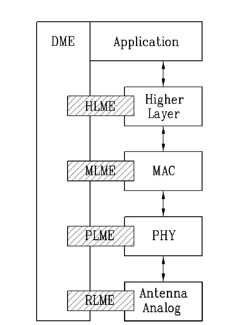
[0076]FIG. 1 illustrates a hierarchical structure according to the present invention.

[0077]The hierarchical structure includes an application layer, a higher layer, a MAC layer, and a PHY layer. The application layer is connected to a Device Management Element (DME), the higher layer is connected to the DME through a Higher Layer Management Element (HLME), the MAC layer is connected to the DME through a MAC Layer Management Element (MLME), and the PHY layer is connected to the DME through a PHY Layer Management Element (PLME).

[0078]In the case of wireless communication having high directionality such as mmWave, there is also a need to consider an RF / analog front end as one layer to achiev...


PUM


Abstract

A method for performing beam tracking in a wireless communication network is provided. In the method, a transmitter station emits beam patterns including respective beam pattern indices to receiver stations and receives a feedback index indicating one of the beam patterns from each receiver station during a predetermined channel time after the emission of beam patterns is completed. A beam pattern feedback is processed using a simple code, thereby minimizing the amount of information and hardware required for beam search and tracking. In addition, in uni-directional beam tracking, it is possible to perform tracking on a number of beam links at once and a sub-channel that can be used for beam tracking and search is allocated to each station to allow a number of stations to simultaneously perform beam search, thereby reducing the amount of used channel time.

Description

TECHNICAL FIELD [0001]The present invention relates to a method and apparatus for allocating beam search times required for wireless transmission having high directionality to perform efficient beam search and tracking.BACKGROUND ART [0002]In a Multiple-Input Multiple-Output (MIMO) communication system, a transmitter station uses multiple transmit antennas and a receiver station uses multiple receive antennas for data communication. A single MIMO channel created by the antennas can be decomposed into independent channels. Each of the independent channels is a sub-channel (or transport channel) in the space domain of the MIMO channel and occupies one scope. The MIMO system can exhibit improved performance (for example, improved transmission capacity) when additional scopes created by multiple antennas are used.[0003]The MIMO system is divided into two types, namely, open-loop and closed-loop. In the open-loop system, space-time coding technologies are generally implemented in the MIM...

Claims


Application Information

Patent Timeline
IPC IPC(8): H04B17/00
CPCH04B7/043H04B7/0619H04B7/0632H04L27/2613H04B7/0617H04B7/0695
Inventor JEON, BEOM JIN
Owner LG ELECTRONICS INC
Why Eureka
Try Eureka