Connector

Active Publication Date: 2011-01-13
YAZAKI CORP
View PDF12 Cites 12 Cited by
  • Summary
  • Abstract
  • Description
  • Claims
  • Application Information

AI Technical Summary

Benefits of technology

[0008]It is therefore an object of this invention to provide a connector in which the durability o

Problems solved by technology

In the above conventional connector, however, the elastic arms of the detection member were elastically deformed in accordance with the bending movement of the lock arm, and therefore when the detection

Method used


Image

  • Connector
  • Connector
  • Connector

Examples


Example

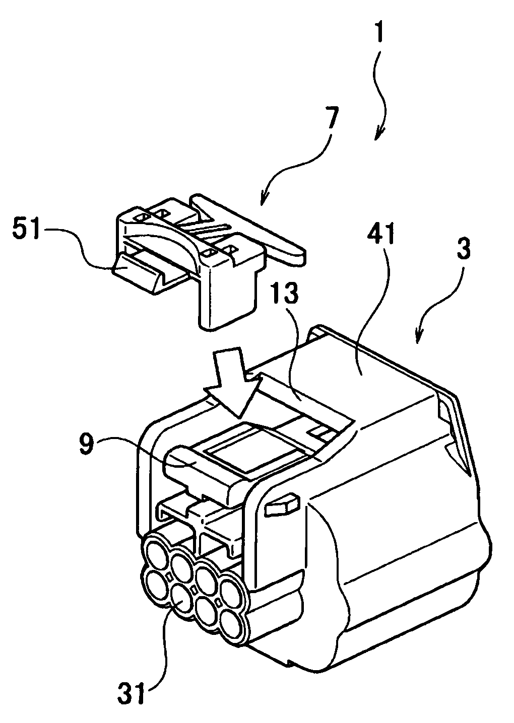
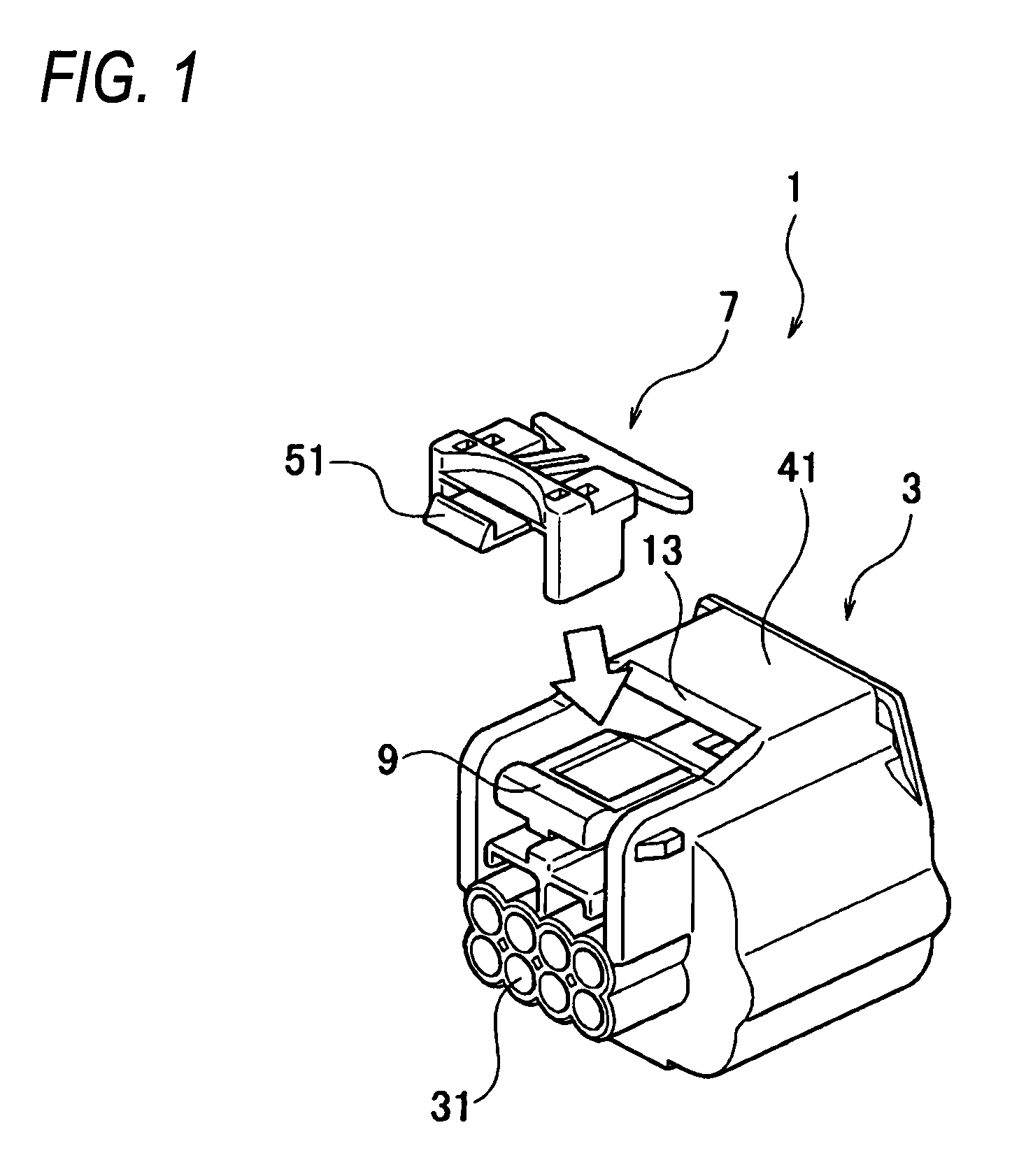
[0053]A first embodiment of the invention will now be described with reference to FIGS. 1 to 8.

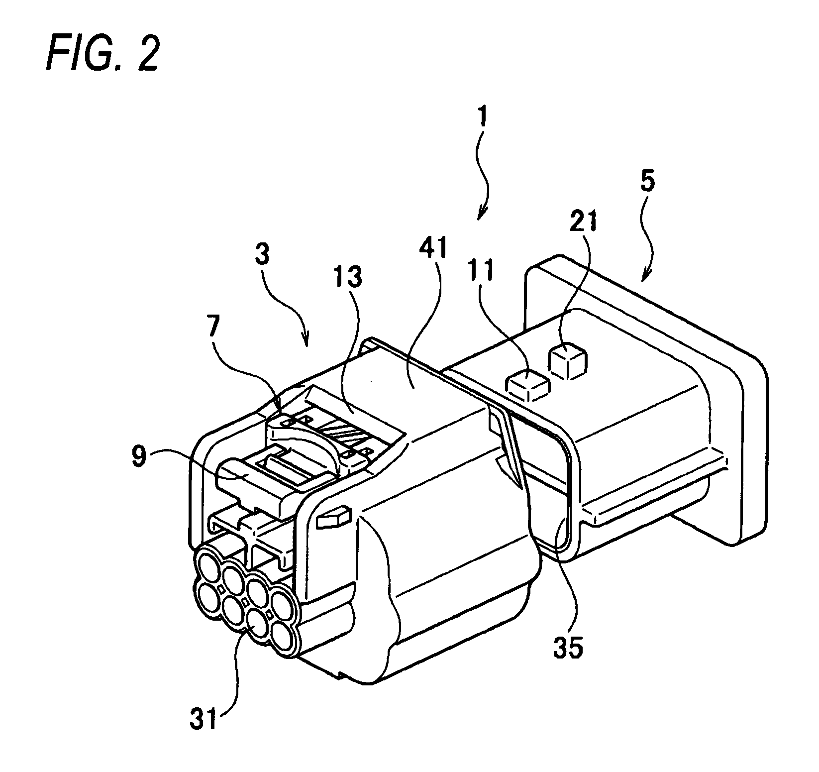
[0054]A connector 1 of this embodiment includes a pair of female and male housings 3 and 5 to be fitted together, and a detection member 7 attached to the female housing (first housing) 3 so as to detect a fitted condition of the pair of housings 3 and 5 through its movement in an attaching direction. A lock band portion 9 is elastically bendably (or deformably) formed on the female housing 3, and a lock portion 11 is provided on the male housing (the second housing) 5, and bends the lock band portion 9 to allow the lock band portion 9 to slide thereover when the pair of housings 3 and 5 are to be fitted together, and retains the lock band portion 9 when the pair of housings 3 and 5 are fitted together. The detection member 7 is disposed on an upper side of the lock band portion 9, and is displaced together with the lock band portion 9 in accordance with a bending movement of the lock band...

Example

Second Embodiment

[0081]A second embodiment of the invention will be described with reference to FIGS. 9 to 16.

[0082]In a connector 101 of this embodiment, a detection member 103 has movement limitation portions 105 which abut against an abutment limitation portion 13 of a female housing 3 to thereby prevent the detection member 103 from movement in an attaching direction when a lock band portion 9 is disposed on the upper side of a lock portion 11. When the lock band portion 9 is retained by a lock portion 11, the abutment of the movement limitation portions 105 against the abutment limitation portion 13 is canceled, thereby enabling the detection member 103 to move in the attaching direction.

[0083]The detection member 103 further has provisional movement limitation portions 107 which abut against the abutment limitation portion 13 (serving as a provisional abutment limitation portion) of the female housing 3 before the fitting of the pair of housings 3 and 5, thereby preventing th...

Example

Third Embodiment

[0102]Next, a third embodiment of the invention will be described with reference to FIGS. 17 to 20.

[0103]In a connector 201 of this embodiment, a detection member 203 has shaking limitation portions 207 which abut against shaking abutment limitation portions 205 provided on a female housing 3 before the fitting of a pair of housings 3 and 5, thereby limiting or preventing the movement of the detection member 203 in a direction intersecting an attaching direction. In this embodiment, those portions identical in construction to the corresponding portions of the first embodiment will be designated by identical reference numerals, respectively, and explanation of the constructions and functions thereof will be omitted. These portions achieve the same advantages as described for the first embodiment.

[0104]As shown in FIGS. 17 to 20, the shaking limitation portions 207 are defined respectively by distal end surfaces of a plurality of projections formed on opposite side fa...


PUM


Abstract

A connector includes a first housing, a second housing and a detection member. A lock band portion is elastically deformable and is provided on the first housing. A lock portion is provided on the second housing, and bends the lock band portion to allow the lock band portion to slide over the lock portion when the first and second housings are moved from a first condition to a second condition, the first condition where the first housing is not fitted to the second housing, and the second condition where the first housing is fitted to the second housing, and engages the lock band portion when the first and second housings has been moved to the second position. The detection member is disposed on an upper side of the lock band portion, and is displaced together with the lock band portion in accordance with a deforming movement of the lock band portion. A movement limitation portion is provided on the detection member, and abuts against an abutment limitation portion provided on the first housing while the first and second housings are moved from the first condition to the second condition, so that the detection member is prevented from movement in the attaching direction. When the lock portion engages the lock band portion in the second condition, an abutment of the movement limitation portion against the abutment limitation portion is canceled, so that the detection member is allowed to be moved in the attaching direction.

Description

BACKGROUND[0001]This invention relates to a connector capable of detecting a half-fitted condition.[0002]Among conventional connectors capable of detecting a half-fitted condition of a pair of housings, there is known the type of connector including a pair of connector housings, and a fitting detection member attached to one of the connector housings (see, for example, Patent Literature 1).[0003]In this conventional connector, a lock arm is provided at the one connector housing, and can be elastically deformed toward a bending space by the other connector housing. Elastic arms are provided at the detection member, and can be elastically deformed in accordance with the bending movement of the lock arm. Reception portions are provided respectively at the elastic arms, and when the elastic arms are elastically deformed, these reception portions are retainingly engaged respectively with retaining portions of the one connector housing, thereby preventing the detection member from being p...

Claims


Application Information

Patent Timeline
IPC IPC(8): H01R13/627
CPCH01R13/639H01R13/6272
Inventor URANO, KAZUMIYAMAGISHI, HIROAKISAKURAI, TOSHINORI
Owner YAZAKI CORP
Why Eureka
Try Eureka